Intelligent Transportation Systems
Intelligent Transportation Systems (ITS) refer to the devices used to facilitate dynamic transportation operations. These devices include traffic control devices such as traffic signals, flashing beacons, and dynamic message signs (DMS), as well as support devices such as the communication system, closed circuit television cameras (CCTV), and data collection devices. When used together in high demand areas, these devices provide a transportation system that operates at its maximum level of efficiency, enhancing safety, predictability, and mobility.
Design Standards
Traffic signal standards are provided in the Federal Highway Administration Manual on Uniform Traffic Control Devices. This includes warrants for justifying signal installations, warrants justifying protected signal phases, standards for signal indications and placement, signal timing standards, pedestrian pushbutton placement, and signage and markings standards associated with traffic signals.
The City of Seattle Standard Plans and Specifications provide standards and drawings for construction practices and materials specifications.
The traffic management system should meet the NEC to the degree that is practicable and consistent with Washington law, WAC 296-46B-901 and RCW 19.28.
Designers are cautioned to be aware of the requirements of the National Electric Safety Code, which can impact the ability and cost of construction. The National Electrical Safety Code (NESC®) is the industry-accepted safety standard for overhead and underground electric utility and communications utility installations. NESC covers electric supply and communication lines, equipment, and work practices employed by both public and private electric utility installations.
Current NESC requires specific distances between utility facilities, such as overhead lines, and other structures, such as houses and pools. These distances vary based on the type of utility facility and the type of structure being built.
Design Guidance
Traffic Signals
Clearances
There are several competing needs regarding the physical location of new poles or cabinets used for ITS elements. The preliminary and most obvious being conflicts with surface, overhead, or underground features. Provide an 18″ setback from the face of the pole to the face of the curb. When there is the standard 5.5′ landscape/furniture zone, provide a minimum 3′ setback from the face of the cabinet to the face of the curb. New poles shall not be placed in the required pedestrian clear zone, pursuant to the applicable Street Type standards (see map to identify street type) and ADA standards.
The next layer of detail to consider is the pedestrian walking path—a linear and unobstructed path that shall be free from any poles. When available, the planting strip that exists between the sidewalk and the curb is commonly a good location for locating ITS infrastructure for meeting both the walking path and ADA needs. In general, it is desirable that poles and cabinets should not be installed on the upstream approach of a marked crosswalk unless 25′ or more upstream from the crosswalk (unless the equipment is setback by more than 5′ from the curb).
King County Metro lines should be attached to the vertical shaft of any signal pole under which they run. When this condition is met, there is no required NESC clearance. King County Metro has a standard clearance of 4.5’ vertical clearance and 5’ horizontal clearance. Deviation from King County standards may be required to meet federal regulations in the MUTCD and SDOT material standards.
Wiring
Pedestrian signal, bike signal, and vehicular signal wiring to an individual pole should be accomplished using a trunk line directly from the signal cabinet with no splices to a terminal cabinet. The wiring should then be split on a terminal strip from the terminal cabinets to each indication. A trunk line is typically a 16 conductor. Individual signals are typically wired using 3, 5, or 7 conductors depending on the number of indications required for the phasing.
Pedestrian push button and emergency preemption wiring will be continuous with no splices from the push button to the controller cabinet.
Traffic signals will be interconnected to the communication system preferably using a layer 3 fiber communication network. Fiber and existing copper interconnect will not be spliced. Any new IP device may require additional communication equipment.
Cabinets
All signals will be powered off of a metered service with a service disconnect cabinet.
Type III controller cabinets will be used unless the location is identified as a potential location for transit signal priority. Where transit signal priority is being proposed or planned for the future, Type VI controller cabinets will be used.
Controller and service disconnect cabinets can be decorated upon request. The preferred method for decoration is vinyl wrap which is best installed in a controlled environment prior to installation. Cabinet decoration has additional cost which would be paid by the requestor.
Detection
All new signals will be fully actuated unless otherwise directed. This includes stop bar loops on both the side street and main line as well as advanced on the main line. This also includes accessible pedestrian push buttons. System detectors may be required for future traffic responsive or adaptive control.
The vehicle detection method at a signal should be proposed by the designer based on the intent of the use of the detector.
Inductive Loops
Inductive loops are the most resilient, cheapest, and easy to construct method of detection. Designers should scope their work to install inductive loops and only use other detection as challenges arise.
When using magnetometers or video detection for challenges on the mainline of traffic, inductive loops should still be used on the side streets in order to limit unnecessary inefficiencies.
Magnetometers
Magnetometers should be used in locations where there are limitations on the underground infrastructure.
SDOT’s approach is to minimize the number of repeaters installed in the field. However, the design should not be done using overly aggressive criteria for repeater placement. As a rule of thumb, designs should be done based on limits for the devices of approximately 20 percent less than manufacturer’s recommendation allows. Be aware of the variation in signal strength between the front, side and back of the repeaters and access points. In the past, designers have created scaled overlays of the device field to support the design.
Designers should be aware of potential interruptions to the sight-line for the wireless communications devices installed. Consider tree canopy changes over the years for existing and planned trees in the design.
Video Detection
Video detection should be used where there are construction challenges that make magnetometers and inductive loops infeasible.
Video detection should not be used in locations where there is direct sunlight that can shine into the camera.
Advanced Detection
The following table provides placement information for advanced detection loops based on posted speed. This distance provided is from the stop bar to the leading edge of the detection zone:
|
Speed (mph) |
Detector 1 |
Detector 2 |
|
45 |
Speed and Vehicle Classification Study Required |
|
|
40 |
85’ |
230’ |
|
35 |
55’* |
185’ |
|
30 |
140’ |
N/A |
|
25 |
105’ |
N/A |
*In the case where there is stop bar detection AND advanced detection, the loop at 55 feet becomes the “third” (or most upstream) stop bar loop.
Accessible Pedestrian Push Buttons
Accessible pedestrian push buttons are required at all new signalized intersections or during updates to traffic signals. See memo: SDOT’s Accessible Pedestrian Signal Design and Implementation Policy.
Accessible pedestrian push buttons should use a rapid tick when more than 10’ apart and a programmed, verbal message when less than 10’ apart.
Bike Detection
Bike detection is required for each movement through a signalized intersection. Bike detectors will be split on to their own channels and appropriately tuned for sensitivity. Bike detectors will be marked with a bike hot spot.
Conduit and Handholes
All traffic signals will be designed with underground infrastructure and mast arms.
Anytime a sidewalk or roadway is paved on an arterial street conduit should be provided for future traffic signal installations and communications.
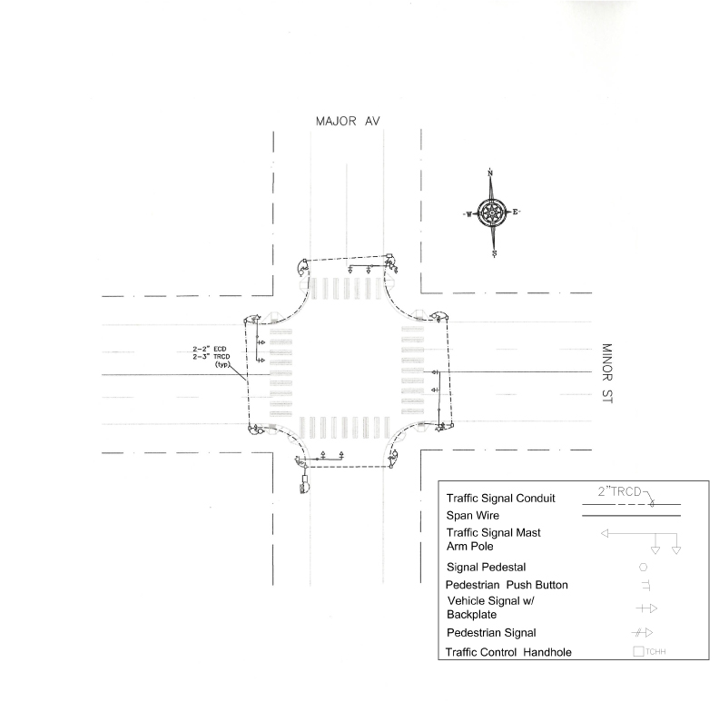
Figure BE is a typical layout for a signalized intersection. To provide a durable and sustainable traffic signal asset the proper underground infrastructure is needed to protect the signal cabling with enough room for future expansion at this location without disruptive and costly civil construction. This underground infrastructure should be provided at any intersection where civil improvements are being made that has an existing signalized intersection or where a future signalized intersection may be planned. A continuous run of conduit and handholes should also be provided along arterial roadways between signalized intersections where sidewalks and/or curbs are being installed or repaired.
Operational Current Practices
Signal Timing
Protected/Permissive Left Turns
-
If a signal is being installed at a location where the Seattle collision warrant is met, protected-permissive phasing shall not be used.
-
If documentation shows that existing protected left turn phasing was installed due to meeting Seattle’s left turn collision warrant, protected-permissive phasing shall not be used.
-
If sight distance is limited or if there are gaps where approaching vehicles are not visible (e.g., due to a sag curve), protected-permissive phasing shall not be used. Protected-permissive phasing shall not be used unless sight distance for a stopped vehicle turning left against opposing traffic meets the calculations based on the posted speed limit and 5.5 seconds of gap timing.
-
If confusion would result due to the character of the channelization or geometry of the intersection, protected-permissive phasing should not be used.
-
If the vehicle making the left turn has to cross four or more opposing lanes protected-permissive phasing shall not be used. Engineering judgement should be used when considering protected –permissive left turn if there are three opposing thru lanes.
-
If the posted speed limit is above 45 mph, protected-permissive-phasing shall not be used.
-
Protected-permissive phasing should not be used if there is more than one left turn lane.
-
If there are numerous access points adjacent to an intersection where cars may enter unexpectedly, the location may not be a good candidate for protected-permissive phasing and should be evaluated on a case by case basis.When evaluating an intersection for protected-permissive left turn operation, field observation and application of sound engineering judgment are necessary. The following factors shall be considered:
Pedestrian Signal Timing
Shorter traffic signal cycle lengths (ideally less than 60 seconds) and longer walk intervals provide better service to pedestrians and encourage signal compliance, which improves safety. For optimal pedestrian service, fixed-time signal operation usually works best because it provides an automatic pedestrian phase. Pedestrian clearance intervals shall be calculated to allow all travelers to safely clear the intersection. 3.5 feet per second is the maximum crossing speed used to calculate the pedestrian clearance interval. Additional crossing time should be allowed at locations with high pedestrian volumes or where the predominant user has slower walking speeds (e.g. older adults or children). Section 4E.06 of the MUTCD provides additional guidance on pedestrian intervals and signal phases.
Pedestrian clearance times: The current MUTCD pedestrian clearance times are based on 3.5 ft/s walking speed. In order to calculate the total pedestrian clearance time:
- Measure the distance from curb to curb at the center of the cross walk.
- Divide the distance by 3.5.
Pedestrian clearance times do not include yellow and all red portions of the concurrent vehicle phase.
We also consider slower walking speed in our calculation of pedestrian clearance time if the intersection is near a facility serving older adults, facilities serving people with disabilities, schools, or based on constituent concern. This is achieved by installing accessible push buttons and configuring an extension time in the signal controller triggered by pushing the button for a longer period of time.
Leading pedestrian intervals: Leading Pedestrian Interval (LPI) allows additional time for pedestrians to begin crossing prior to the motor vehicle green indication. Consider using LPI at intersections with high pedestrian volumes and/or incidence of right turning vehicle conflicts.
If a leading pedestrian interval is used, the use of accessible pedestrian signals should be considered. It should be at least 3 seconds in duration and should be timed to allow pedestrians to cross at least one lane of traffic or, in the case of a large corner radius, to travel far enough for pedestrians to establish their position ahead of the turning traffic before the turning traffic is released.
Early termination of pedestrian interval: At intersections with pedestrian volumes that are so high that drivers (vehicle or transit) have difficulty finding an opportunity to turn across the crosswalk, we terminate the ped clearance early and keep the green light on to provide opportunity for turning drivers to make their turns while the pedestrian signal head is displaying a steady DONT WALK signal indication.
Exclusive Pedestrian Phase: Can be a “pedestrian scramble” or an “all way walk”. Both are exclusive pedestrian phases which allow all pedestrians to cross while all vehicular traffic is stopped. These treatments improves pedestrian safety but may increase delay for all other intersection users. A “pedestrian scramble” should be evaluated where there are high volumes of pedestrians, equal desire lines in all directions, conflicting vehicle movements are high (greater than 250 vehicles per hour), near senior housing, schools, recreational areas, or medical facilities, or at intersections with restricted sight distance and/or complex intersection geometry. Exclusive pedestrian phases should consider potential issues with permissive left turns, especially where buses or trucks are making lefts turns to avoid vehicles getting trapped in the intersection. Countermeasures can include increasing the all-red time, selecting a phase order to eliminate or minimize the conflict, or installation of protected turn phases. An engineering study should be completed to evaluate the impact to all modes and to determine if a pedestrian scramble is the most appropriate solution.
Pedestrian Push Buttons: Push buttons are most appropriate at complex intersections, intersections with lower pedestrian volumes, or signalized mid-block crossings (e.g. trail crossings), and are generally not desirable in areas with high pedestrian volumes or when pedestrians are frequently present. Whenever feasible, in locations where pedestrian volumes are significant or compliance is poor, push buttons should be enabled to activate a “hot response” from the pedestrian signal, providing a pedestrian phase quickly after the button is pushed. Push button placement must follow MUTCD and ADA guidelines to ensure accessibility. Section 4E.08 of the MUTCD provides additional guidance on pedestrian detectors.
Bicycle Push Buttons: Where it is determined passive bike detection is not feasible, a bicycle push button may be mounted on a pole. It shall be placed so that bicyclists can reach it while remaining mounted from within the bicycle facility. The push button should be supplemented with an R10-24 sign.
Accessible Pedestrian Signals (APS): APS provide pedestrian signal information in audible and vibrotactile formats for hearing- and sight-impaired people. The designer should refer to for information on when APS is triggered and how APS equipment will be installed and activated within the City of Seattle public right-of-way. Section 4E.09-13 of the MUTCD provides additional guidance on accessible pedestrian signals. See SDOT memo on: SDOT’s Accessible Pedestrian Signal Design and Implementation Policy for details on APS improvements.
Queue Jump
A separate phase is given to the transit vehicle to jump start and get ahead of the platoon of vehicles waiting at the stop bar if the bus has to make lane changes at the upstream of the intersection, thereby named queue jump or QJ for short. A separate visibly limited signal head is installed for the transit vehicles. This signal head turns green for the dedicated QJ phase and stays on when the compatible thru traffic also turns green. At which point the transit vehicle must negotiate it’s way to merge in at the upstream of the intersection.
Transit Signal Priority
Traffic signals may be timed to provide a green indicator to an approaching transit vehicle in order to reduce delay to buses at signalized intersections. Transit Signal Priority, transit signal queue jump and other related treatments should be evaluated at all major signals along Urban Center Connector, Downtown, and Urban Village Main street types.
Our current practices is to provide transit signal priority (TSP) to transit vehicles that are behind schedule, to enhance the reliability of their operation. The transit vehicles include LRT/Streetcar, rapid rides buses, BRT and any other buses requested by King County Metro. The operational scheme to providing TSP depends on the type of controller software at the intersection and they are as explained below:
- Partial Priority: This is when the green light that is about to be terminated will be extended upon receipt of the TSP call. Or if the light is already red for the transit vehicle, then the other phases will be shortened to service the transit vehicle the fastest possible. This type of operation is preferred for coordinated arterials such as Urban Center Connectors and some Urban Center Main streets. Since the coordination is maintained during this operation and adverse operational effects are minimized.
- Full Priority: This is much more aggressive and could skip pedestrian phase(s) or vehicle phase(s) to get to the transit vehicle phase the fastest. As such is only recommended for intersections that are isolated on Urban Center Connectors or where there is high capacity transit.
See transit section of Streets Illustrated for information on Real Time Information Signs and Bus Stop Improvements.
Concept of Operation
Signals along an arterial or networks should be interconnected to other signals using single mode fiber. The number of strands is to be determined per project basis or direction from the ITS manager or designer. Signals should be fully actuated and have system detectors on the far side of the intersection(s) and exit detectors per design guidelines. This is to have flexibility for operating the corridor or network using traffic responsive or adaptive operation.
Pole Attachments
There will be no 3rd party attachments to a mast arm.
Utilities and trolley lines may attach to signal poles so long as there is no electrical hazard and a structural analysis has been performed. Requests will be analyzed on an individual basis.
Radar Speed Signs
Radar Speed Displays Signs are one of the many traffic calming tools SDOT uses to help encourage lower traffic speeds and improve safety on arterial roadways. The signs include an active display that indicates to drivers the speed at which they are traveling and are installed with a posted speed limit sign so drivers can see their speed compared to the posted speed limit. Typically, the display is set to come on only once a vehicle is traveling at the speed limit and flashes the drivers speed if it exceeds the posted limit. SDOT has typically used these signs on arterial streets where studies indicate a combination of high speeds and collision history.
Beacons
School beacons
School beacons are located only on arterial streets where we have established a 20 mph school speed zone. School speed zones are typically established within 300 feet of a school property, or within 300 feet of a crosswalk patrolled by a crossing guard.
The Safe Routes to School Action Plan prioritizes new flashing beacon locations. This prioritization includes Pedestrian Master Plan data, collision data, and an equity factor that gives more weight to schools based on the percent of non-white students.
Some beacons have been installed through the Neighborhood Park and Street Fund. We also look for leveraging opportunities and sometimes require flashing beacons to be installed as part of SIPs or MUPs when schools are remodeled or rebuilt.
Rectangular Rapid Flashing Beacons:
Rectangular Rapid Flashing Beacons (RRFB) are one of the many pedestrian crossing enhancements SDOT uses to improve vehicle yielding, crossing safety and pedestrian comfort at crosswalks. Installed in concert with signing and pavement markings, these beacons are intended to decrease recognition time for approaching drivers and clearly indicate a pedestrian intent to cross the roadway. RRFBs are installed with the approval of the traffic operations group and may be combined with other enhancements at a given marked crosswalk. Evaluation criteria include roadway geometry, speeds and volume as well as pedestrian crossing activity, proximity to walking routes and collision history. See the Bicycle Intersection Design section for more design guidance for RRFBs on greenways.
Closed Circuit TV
The first step in the design process for closed circuit television (CCTV) is preliminary field observations of candidate locations. Initially, the candidate locations can be identified on a suitable aerial photo.
Generally, for CCTV at existing roadways, the first field check shall be made by the designer using still digital photographs to capture the potential views (shoot images both with wide angle and zoom) from the street level at the camera mounting location.
Depending upon the quality of the location, the proposed CCTV location should be evaluated using a bucket/hoist truck. Such a survey of a potential location will be done with a video camera taking images of at least 30 seconds along each of the corridors (again, the camera should be placed at approximately the same location as will be the CCTV) visible from the CCTV. Again, the wide angle and zoomed in images should be captured. Cameras should be mounted at about 25 feet.
Proposed CCTV camera locations that can appear to intrude noticeably on private property should be equipped with a fixed shield. Such locations include sites adjacent to office or apartment building windows.
CCTV may be mounted upon new or existing mast arms, strain poles, wood poles, and upon new bracket arms attached to any of the previous poles and may also be mounted to any monotube or cantilever sign support. Attachment to any poles will require approval from the owner.
Dynamic Message Signs
The required character height is 12 inches for speeds up to 35 MPH. For speeds above 35 MPH, the letter height shall be 16 inches. All signs shall be capable of displaying 16 characters using standard fonts.
The signs should be mounted over the curb lane. If additional offset is required, a sign with a 70 degree viewing angle should be implemented.
A Type 336A cabinet (without police panel) shall be used for the Dynamic Message Sign (DMS) controller. The Type 336A cabinet shall have a minimum type 2 HH.
Travel Time Devices
SDOT has a system of travel time detectors that are placed along strategic corridors throughout the City. Any time a new signal is installed or a controller cabinet is upgraded along these corridors a travel time detector will be provided with a 5-year service plan.
Transit Improvements
Real Time Information Signs and Bus Stop Improvements
See transit section of Streets Illustrated.
Transit signal priority
Traffic signals may be timed to provide a green indicator to an approaching transit vehicle in order to reduce delay to buses at signalized intersections. Transit Signal Priority, transit signal queue jump and other related treatments should be evaluated at all major signals along Urban Center Connector, Downtown, and Urban Village Main street types.
Construction Mitigation
Contractors must provide a written plan for maintain all ITS devices during construction. This includes signals, detection, communication, cameras, travel time devices and dynamic message signs. Temporary non-standard installations may be allowed on a case by case basis.
In order to maintain efficient transportation operations, projects may be required to provide additional temporary ITS devices and improvements to existing ITS devices during construction. This may include temporary CCTV, additional signal phasing, or upgrade to adjacent systems.
