Bike Intersection Design
- Protected Bicycle Lane Intersection Design
- One Way Protected Bike Lane Mixing Zone
- One Way Protected Bike Lane Transition to Bike Lane or Shared Lane
- One Way Protected Bike Lane Intersection Design
- Protected Bike Lanes and Downhill Descents
- In Street Minor Separation Intersection Approaches
- Supporting Intersection Treatments for Bicycle Facilities
- Bicycle Box
- Median Diverter Island and Standard Median or Crossing Islands
- Offset Street Connection
- Curb Bulbs
- Cross Bicycle Intersection Markings
On this page:
Design Guidance
Conflicts between bicyclists and pedestrians and motorists can be reduced using geometric design and/or signal phasing.
Geometric design: Conflict locations should be separated so travelers are only required to negotiate one potential conflict at a time including potential conflicts between bicyclists and pedestrians. Where feasible, designs should provide:
- Continuous separation to the cross street between bicyclists, motorists, and pedestrians.
- Space for motor vehicle to wait out of the flow of traffic while yielding to bicycles at turning conflicts.
- A crossing area for bicyclists that is separated from the pedestrian crosswalk.
- Separate space for queuing and turning bicycles.
The design of intersections should ensure visibility between approaching and departing motorists, bicyclists and pedestrians. All people should be provided visual cues that clearly indicate right-of-way priority and expected yielding behavior. The following strategies can be used to accomplish this:
Stopping sight distance: When designing protected bicycle facilities, stopping sight distances at intersections and driveways should be reviewed to maximize visibility of bicyclists and reduce conflicts between all travel modes. Sight and stopping distance calculations may vary based on the characteristics and constraints of each intersection. The standard stopping sight distance should be used from the following table:
| Grade | Stopping Sight Distance |
| Flat (0%) | 90 ft |
| Steeper slopes (≥5%) | 125 ft |
Table assumes 17 mph design speed and 1.0 seconds of reaction time.
Parking restrictions: For locations where protected bike lanes are located adjacent to the travel lane and on street parking is adjacent to the landscape/furniture zone, parking should be restricted a minimum of 20 feet from a marked or unmarked crosswalk at intersections. At locations where turning speeds are higher, additional restrictions may be needed based on site specific geometric or operational characteristics.
Clearly delineate crossings: Marked crossings should indicate the preferred crossing location for bicyclists and pedestrians across all potential conflict points. Details of crossing markings are provided in the Cross Bicycle Intersection Markings section.
Clearly indicate right-of-way priority: Signs and markings should reinforce correct yielding behaviors.
Provide yielding geometry: Intersection geometry should not require people to turn their head more than 90 degrees to see a potential conflict. The angle of conflict between through moving bicyclists and turning traffic should be between 60 and 90 degrees. This may be accomplished by providing a lateral offset between the vehicle lane and bicycle crossing.
Reduce speeds at conflict points: Reducing motorist turning speeds improves the ability of motorists to appropriately yield to bicyclists, which is particularly important at street intersections, driveways and alleys. Likewise, it is beneficial to slow the speed of approaching bicyclists to ensure turning motorists have time to see and react to them prior to the conflict point. Lower speeds reduce stopping sight distance requirements and reduce severity of injuries in the event a crash occurs. Speed reduction is achieved primarily through horizontal and vertical deflection, which may also be supplemented with pavement markings and signage.
Vertical deflection: Raised crossings can slow turning motor vehicles and approaching bicyclists on the approach.
Signal phasing: A protected bicycle phase may be used to separate bicycle and vehicle movements. A bicycle signal phase is typically applied where achieving desirable yielding behavior is challenging due to geometric or operating conditions including sight lines, vehicle volumes and speeds, bicyclist delay, and PBL operations (e.g. 2-way vs. 1-way) among others.
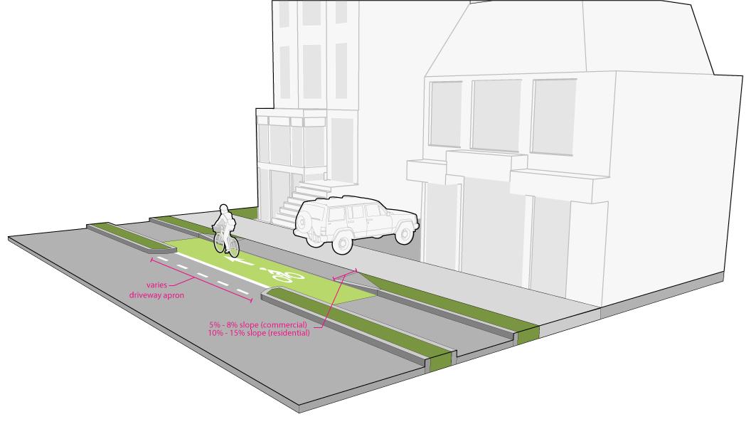
Driveway approaches: at driveway crossings with 5 or more housing units and commercial buildings, a green panel shall be painted for a PBL crossing a driveway shown above in Figure AO. At certain high volume driveways it is beneficial to include raised crossings to provide additional awareness of the crossing for both people on bikes and people in vehicles. If a raised crossing is used, the raised crossing should include markings and ramps.
Protected Bicycle Lane Intersection Design
A key reason for extending protected bike lanes to the intersection is to reduce the number of conflict points between bicyclists and motorists at intersections. On roadways with traditional bike lanes or shared lanes, bicyclists often must merge, weave and otherwise cross paths with motor vehicles that are traveling at a greater speed. These maneuvers are uncomfortable for most bicyclists due to the combination of the speed differential and bicyclists exposure. In contrast, protected bike lanes at intersections reduce bicyclist exposure by reducing multiple merging and crossing movements to a single predictable crossing point.
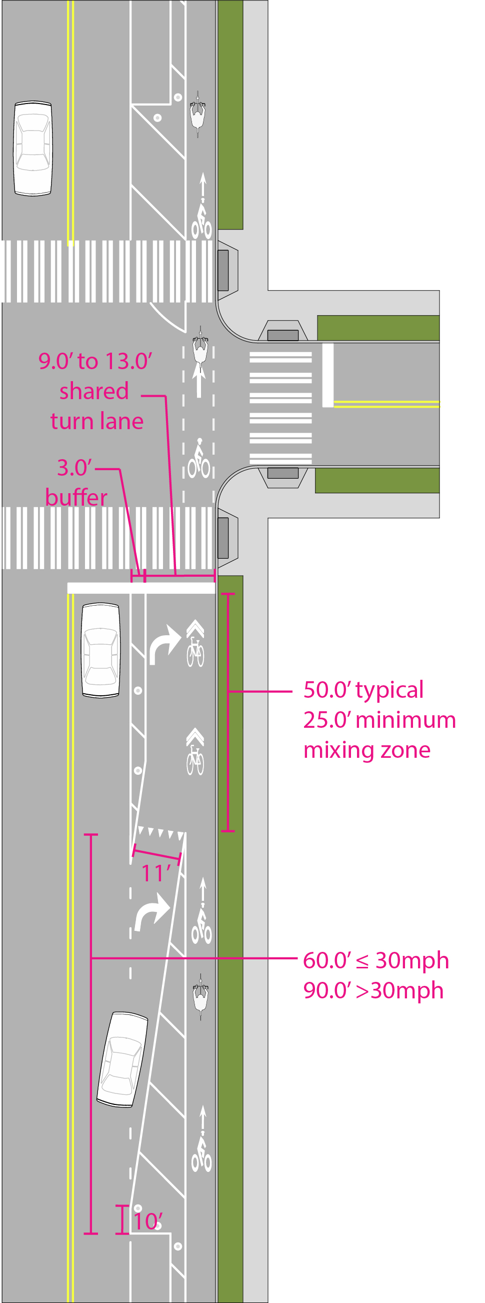
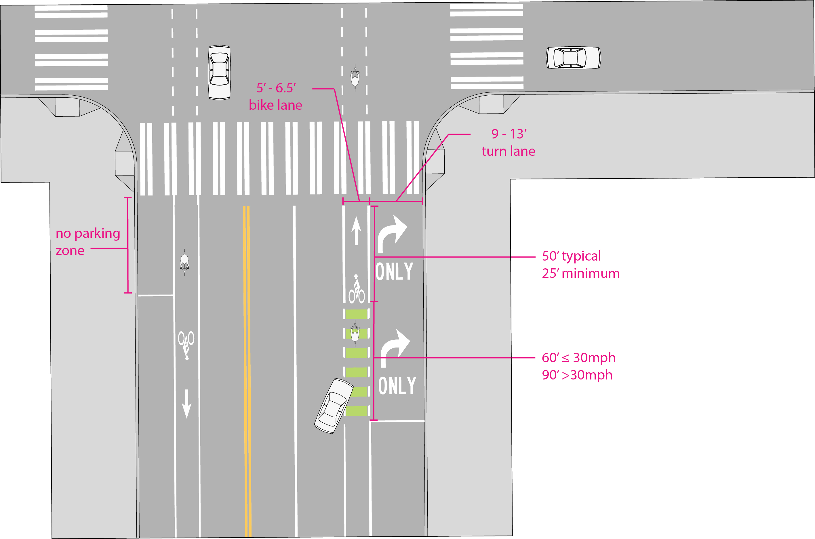
One Way Protected Bike Lane Mixing Zone
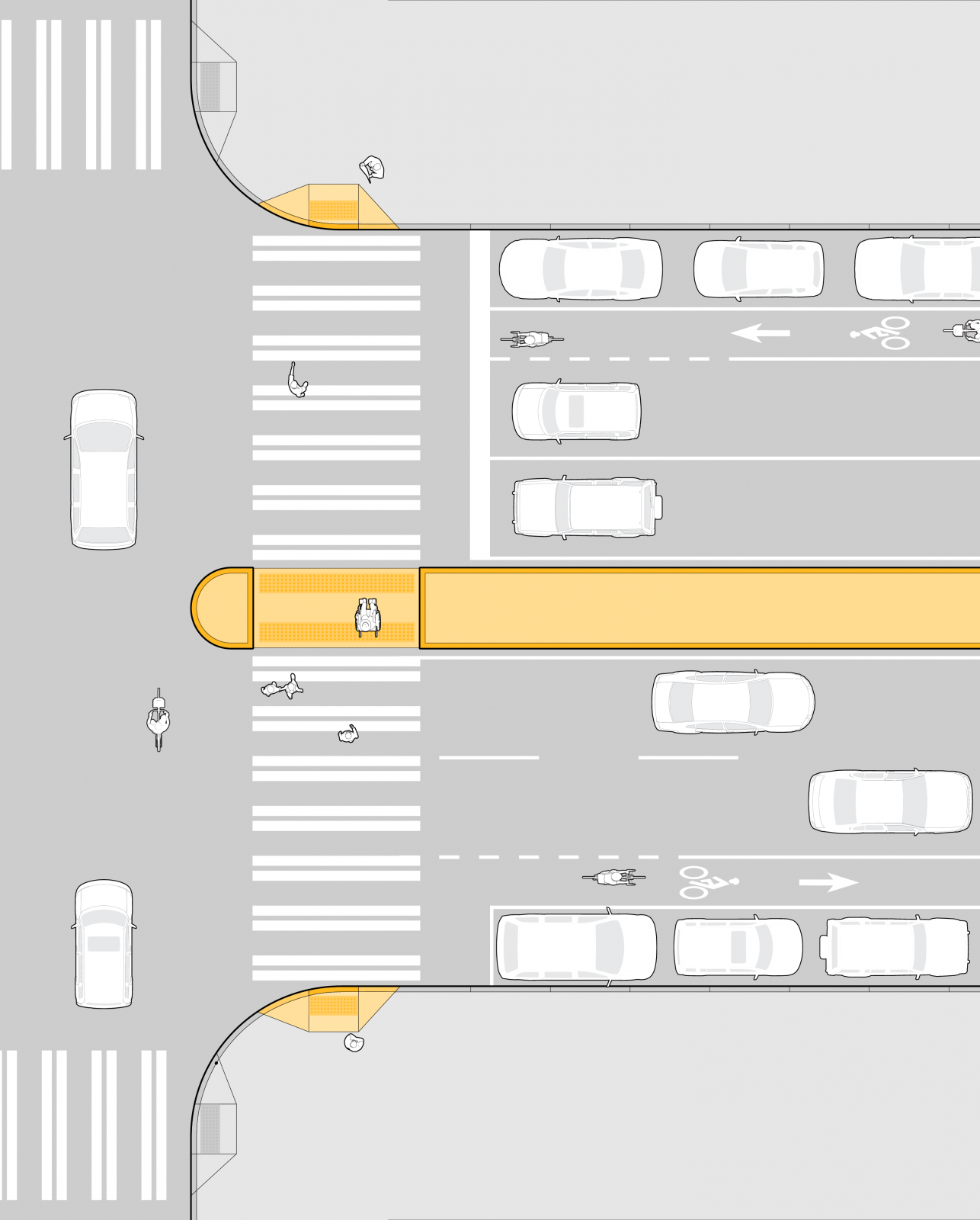
Protected bike lanes may include a bike lane mixing zone. As a strategy to manage conflicts between turning motorists and through moving bicyclists, the protected bike lane may transition to a mixing zone prior to the intersection. A mixing zone requires motorists to yield to approaching bicyclists from a protected bike lane at a confined merge location in advance of the intersection.
Design Standards
- The merge location should be located a minimum 30 feet in advance of the intersection. Parking should be prohibited 10 feet minimum in advance of the beginning of the motor vehicle taper.
- The mixing zone should be demarcated with striping to develop the turn lane and a yield line to delineate the location where the motor vehicle must yield to approaching bicyclists. The yield line should be supplemented with a BEGIN RIGHT TURN LANE YIELD TO BIKES sign (R4-4).
- At locations where raised protected bike lanes are approaching the intersection, the bike lane should transition to roadway elevation at the point where parking terminates. The ramps should be limited to a maximum slope of 1:10.
Design Guidance
- A bicycle lane may be developed on the left side of the turn lane after the merge or the lane may remain shared between bicyclists and motorists.
- Green pavement markings may be used to improve positioning of bicyclists and motorists.
- A mixing zone is not appropriate for two-way protected bike lanes.
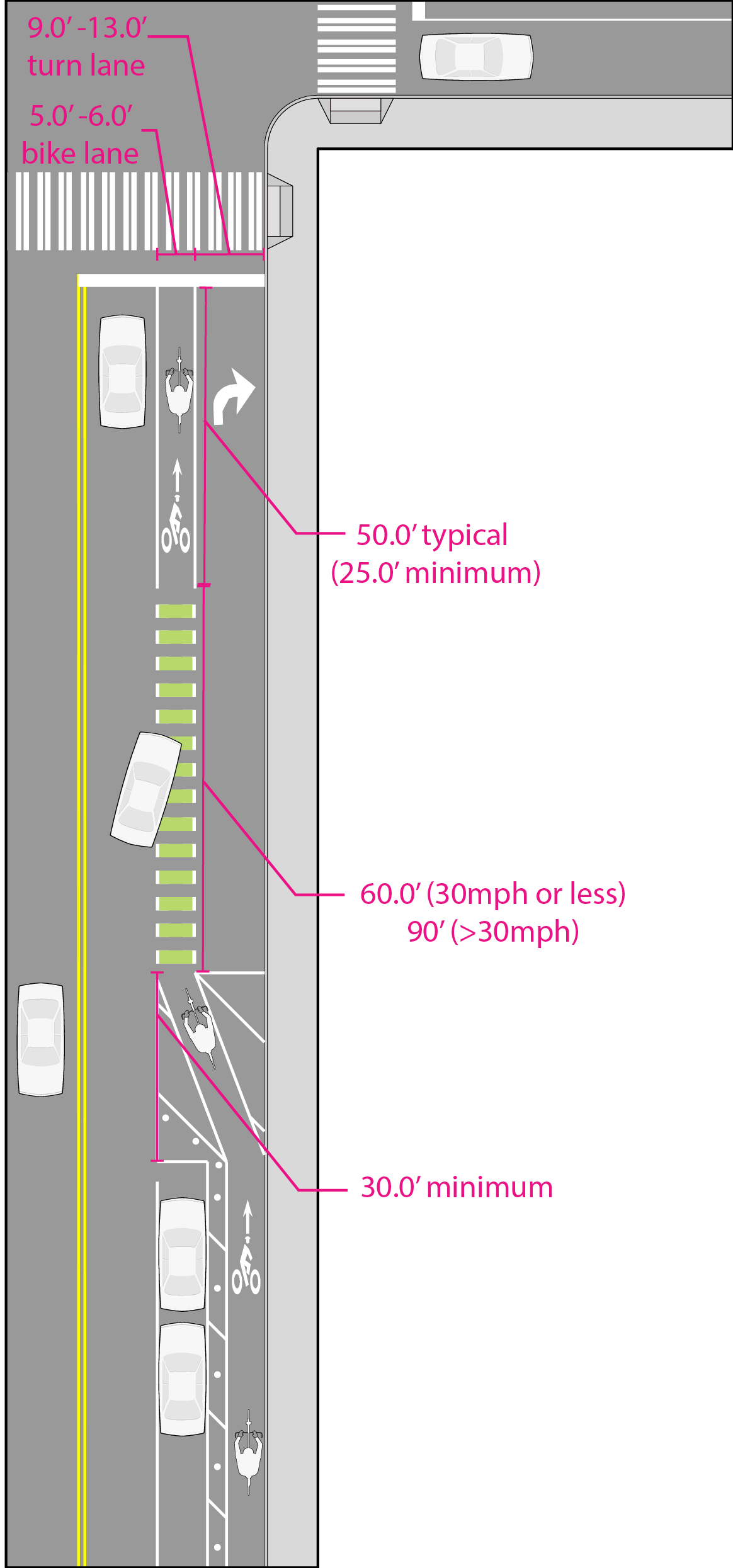
One Way Protected Bike Lane Transition to Bike Lane or Shared Lane
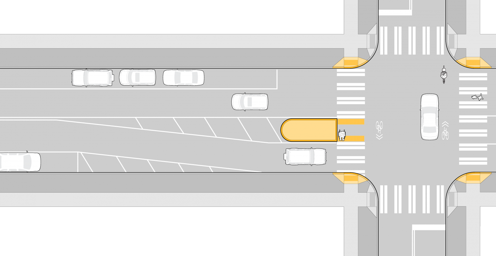
Where one-way protected bike lanes must terminate prior to an intersection to provide additional capacity for motorists or as a strategy to mitigate conflicts between turning motorists and through moving bicyclists, the protected bike lane may transition to a standard bicycle lane or shared lane prior to the intersection. The transition occurs by terminating the vertical protection in advance of the intersection to develop a separate bicycle lane and turn lane, or a shared turn lane. This treatment is appropriate where there is no on-street parking adjacent to the terminating protected bike lane facility.
Design Standards
- The protected bike lane should terminate as close to the intersection and provide as small of a merging area as feasible.
- Approaching the intersection, the protected bike lane should taper towards the motorist vehicle lane to create a merge area parallel to the vehicle lane. The point of termination will be determined by the necessary lengths of the turn lane and merge area.
- The length of the merge area should be 60’ for roads with a posted speed of ≤30mph or 90’ for roads with a posted speed >30mph to provide a clearly defined merge area.
- A BEGIN RIGHT (or LEFT) TURN LANE BEGINS (R4-4) YIELD TO BIKES sign should be located at the beginning of the merge area. The merge area may be highlighted with green pavement markings between the dotted line markings.
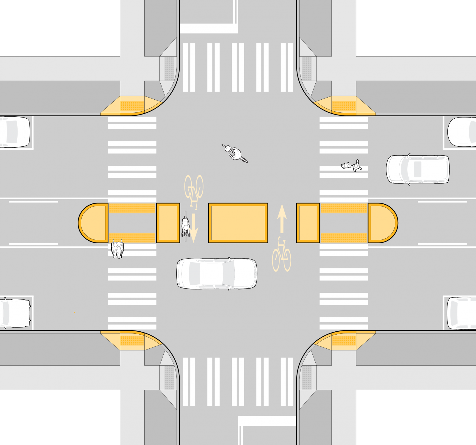
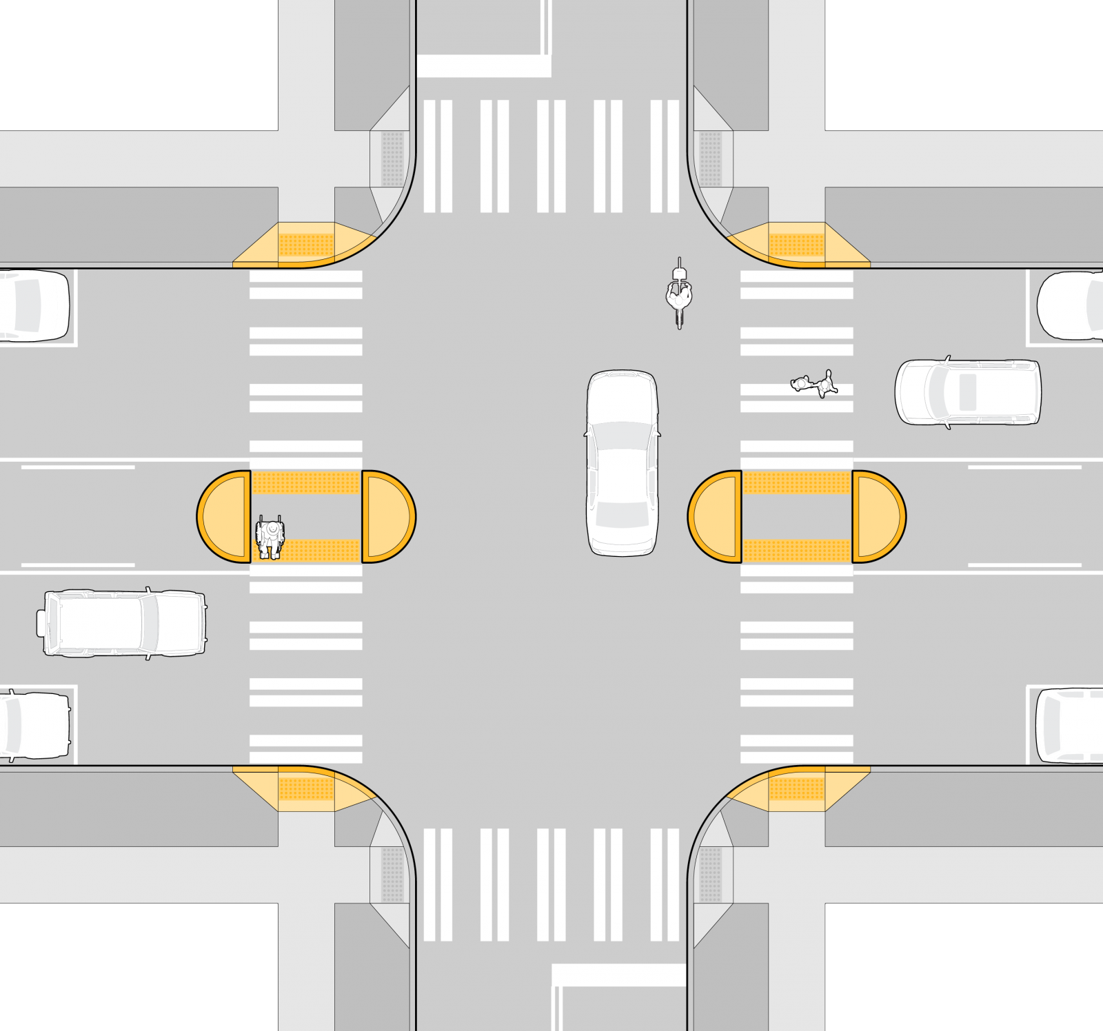
One Way Protected Bike Lane Intersection Design
When protected bike lanes cross, then intersection design should be similar to Figure AQR. By extending protected bike lanes to the intersection, the number of conflict points between bicyclist and motorists can be reduced using geometric design and/or signal phasing.
Design should provide:
- Continuous separation to the cross street between bicyclists, motorists, and pedestrians
- Space for motor vehicles to wait out of the flow of traffic while yielding to bicycles at turning conflicts
- A crossing area for bicyclists that is separated from the pedestrian crosswalk
- Separate space for queuing and turning bicycles
Sidewalk level PBLs should drop to street level upon approach to the intersection to better differentiate pedestrian and bicycle space.
If there is a pedestrian refuge island between the bicycle lane and the car lane then the refuge island must be at least 8′ and include accessible pedestrian push buttons and detectable warning surfaces to indicate the edge of the travel lane. The buffer between the bike lane and the travel lane is a minimum of 2 feet.

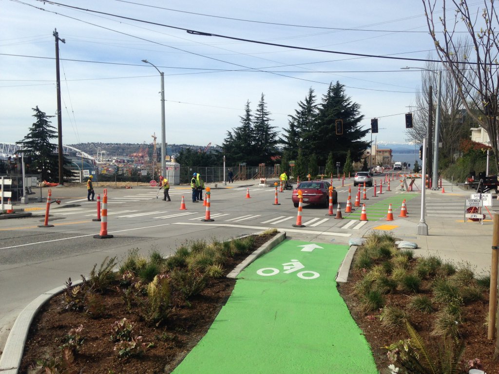
Protected Bike Lanes and Downhill Descents
On streets with steeper grades (greater than approximately 5%) some bicyclists traveling in the downhill direction will be comfortable traveling at speeds well above their typical level-terrain average. On some streets this speed may approach the speed of motor vehicles in the general purpose lanes. Although a protected bike lane provides a higher level of separation from motorized traffic, and therefore improved comfort and safety, the design of a protected bike lane may also create challenges for higher-speed bicyclists to pass slower bicycle traffic within the protected bike lane. If space allows it, a 6.5’ bike lane is recommended.
Shared lane markings should be included in the general purpose lane to alert motorized traffic to the potential presence of bicycles; the locations of the share lane marking should be designed to direct higher-speed bicyclists along a path that provides adequate sight distance for both the bicyclists and crossing traffic, and also encourages the bicyclist to stay at a distance that reduces conflict with parked cars, where present.

In-Street Minor Separation Intersection Approaches
Through Bicycle Lanes Adjacent to Turn Only Lanes
A bicycle lane located to the left of right turning lanes or the right of left turning lanes.
Design Standards
- At locations where a separate bicycle lane is located adjacent to a turn lane, the bicycle lane should be continued to the intersection. This will require the bicycle lane transition to the left of the right-turn only lane or to the right of a left turn only lane within a merging area. The length of the merging area should be minimized to the greatest extent feasible.
- A “Begin Right Turn Lane/Yield to Bikes” sign (R4-4) is recommended at the beginning of the merge area. A “Right (or Left) Lane Must Turn Right (or Left)” sign (R3-7R) should be located adjacent to the turn lane per the MUTCD.
Design Guidance
- Green markings within the merge area and the bicycle through lane may increase visibility and awareness.
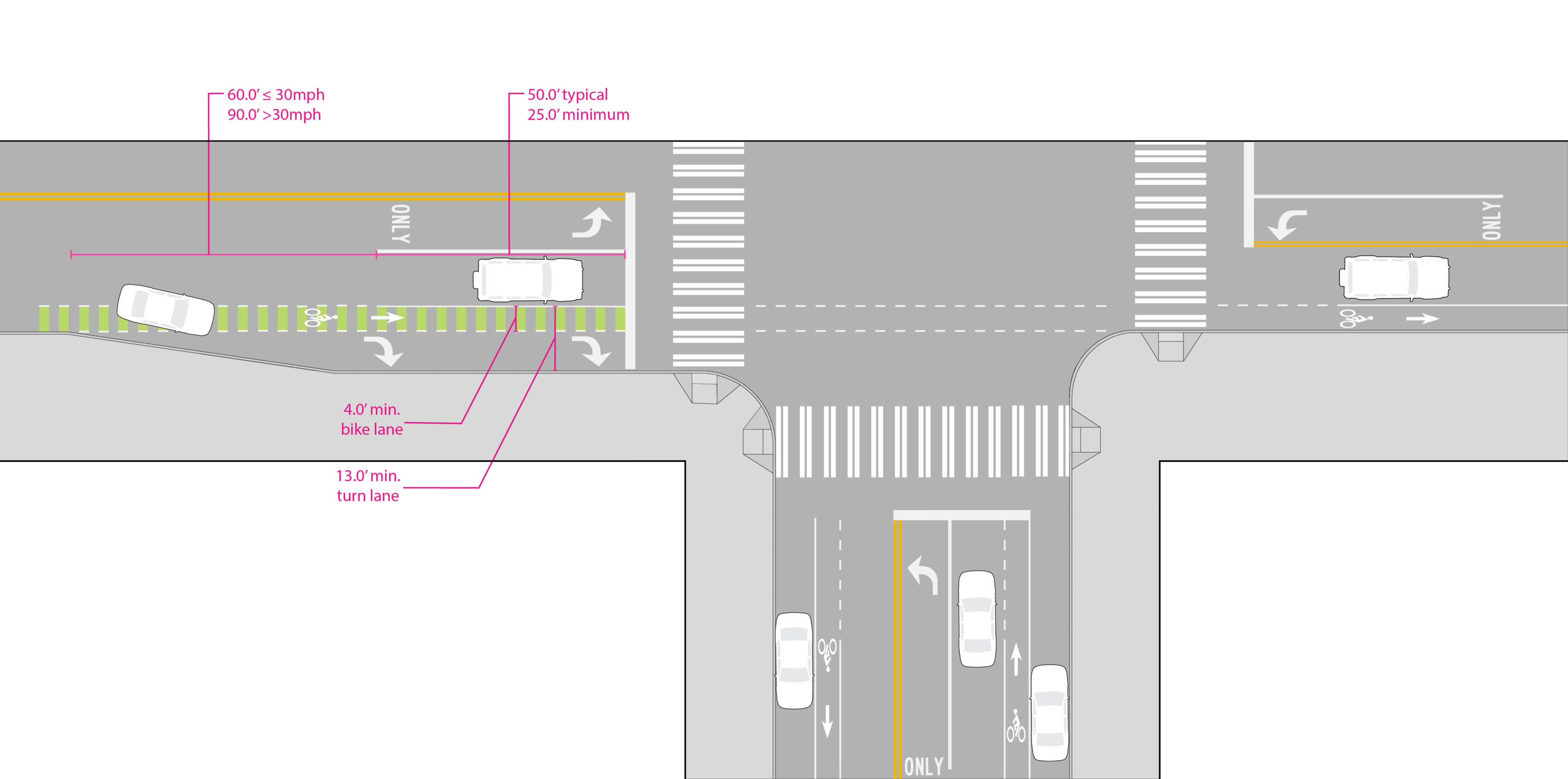
Combined Bicycle Lane/Turn Lane
A bicycle lane located within the inside portion of a turn-only lane to guide bicyclists to the intersection and improve positioning of motorists within the turn lane.
Design Standards
- For right turn lanes that are 13 to 14 feet in width a bike lane should be marked with skipped striping within the combined lane at a minimum width of 4 feet.
- An “EXCEPT BIKES” plaque should be posted beneath any mandatory turn lane signs to permit through travel by bicycles.
- A BEGIN RIGHT (or LEFT) TURN LANE BEGINS (R4-4) YIELD TO BIKES sign should be located at the beginning of the merge area.
Design Guidance
- Skipped green markings may be used to define the bike lane within the turn lane.
- A green cross bike treatment can be added based on engineering judgment.
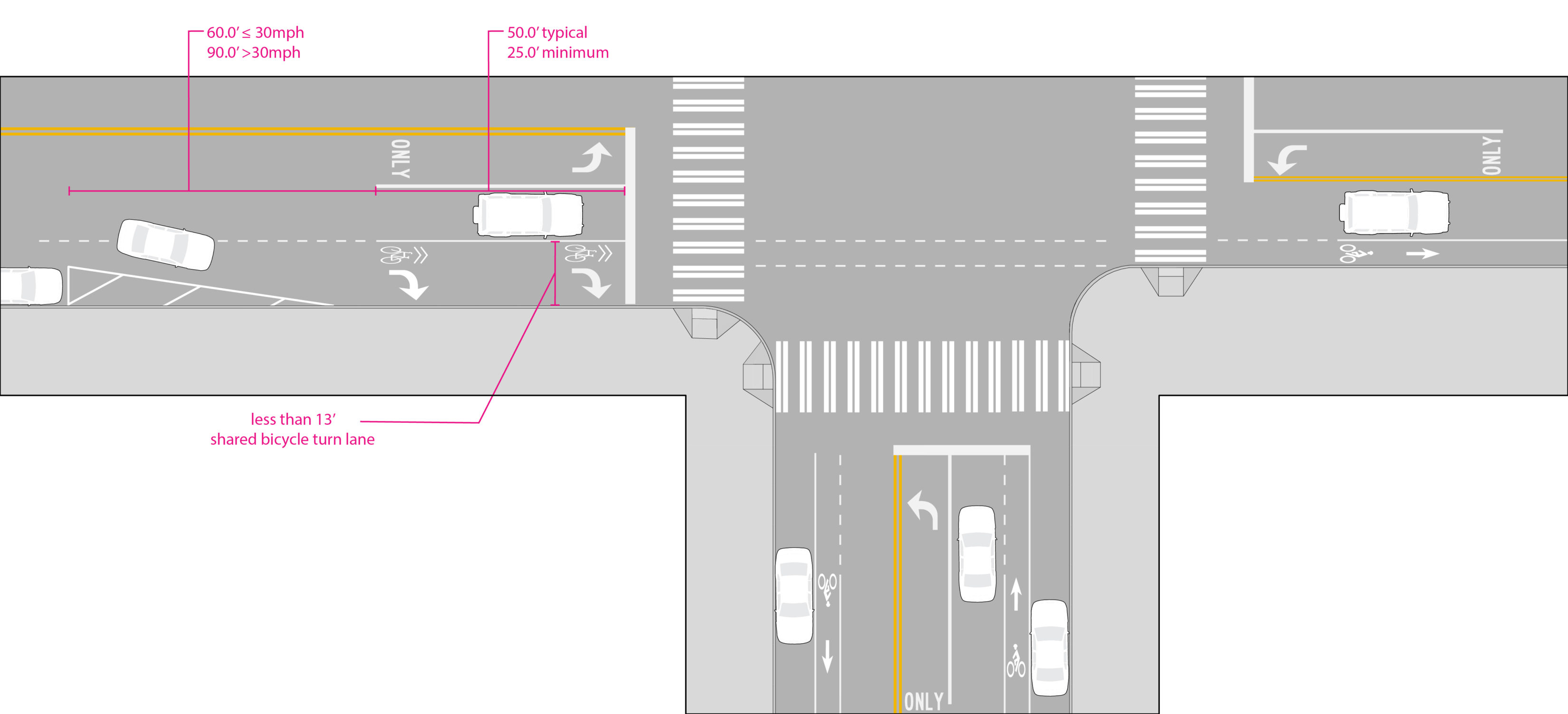
Shared Bicycle Turn Lane
The placement of shared lane markings within the inside portion of a turn-only lane to guide bicyclists to the intersection and improve positioning of motorists within the turn lane. A shared turn lane allows bicyclists to travel through a turn lane by providing an exception to mandatory turn requirements for bicyclists.
Design Standards
- For right turn lanes which are less than 13 feet, shared lane markings should be placed within the center or left hand portion of the turn lane.
- An “EXCEPT BIKES” plaque should be posted beneath any mandatory turn lane signs to permit through travel by bicycles.
- A BEGIN RIGHT (or LEFT) TURN LANE BEGINS (R4-4) YIELD TO BIKES sign should be located at the beginning of the merge area.
Design Guidance
- Shared lane markings may be placed on green pavement markings to further raise motorist awareness of the shared lane.
Supporting Intersection Treatments for Bicycle Facilities
Bicycle Detection
Bicycle detection at actuated traffic signals may be achieved by passive detection strategies such as magnetic loops within the pavement, video, infrared, or microwave technologies. Manual detection may be provided through provision of a push button located on a pole, although the location must ensure easy access for bicycle riders to bush buttons at the curb.
Design Standards
Magnetic Loop Signal detection sensitivity: Loop detector systems, and any other detection system employed such as camera-based motion detection systems, must be sensitive enough to recognize bicycles or bicyclists. These systems should also accommodate the trend in bicycle technology which is resulting in bicycles being manufactured with decreasing amounts of metal.
Pavement markings for loop detector systems: As required by State law, RCW 47.36.025, with new construction or upgrade of detection equipment; bicycle loop detector systems should be accompanied by pavement markings that indicate the location where a bicycle should be located to maximize its disruption of the inductance field. Specifications for this pavement marking are illustrated in Standard Plan 772. Pavement markings may be supplemented with an R10-22 sign.
Push Button Actuation System: Where it is determined passive detection is not feasible, a push button may be mounted on a pole. It shall be placed so that bicyclists can reach it while remaining mounted from within the bicycle facility. The push button should be supplemented with an R10-24 sign.

Bicycle Signal
A traffic signal which displays bicycle signal faces intended to provide guidance to bicyclists.
Design Standards
- Bicycle signal heads shall be placed in a location clearly visible to oncoming bicyclists.
- If the bicycle phase is not set to recall each cycle, passive actuation of bicycle signal is the preferred treatment.
- If the bicycle signal is used to separate through bicycle movements from right turning vehicles, then right turn on red shall be prohibited when the bicycle signal is active. In addition to appropriate regulatory signage, directional turn arrows or an active display should be used to emphasize this restriction.
Design Guidance
- Bicycle signals should be used to mitigate identified safety or operational problems involving bicycle facilities.
- In a close network of signals, the timing should consider how often a bicyclist will be stopped in the system to ensure that undue delay is not a result of the bicycle-only signal.
- For improved visibility, near-sided bicycle signals may be used to supplement far-side signals.
Leading Bicycle Interval
A bicycle signal displays a green for a minimum of 3 seconds before adjacent motor vehicle traffic gets a green signal. Early display gives bicycles a head start to increase visibility and compliance by drivers. A leading bicycle interval may be provided in conjunction with a leading pedestrian interval.
Design Standards
The leading bicycle interval should provide a 3 second minimum crossing advance while conflicting turning movements are held. The timing should be based on the travel speed of bicyclists and the crossing distance – the width of at least one travel lane – and may be up to 6 seconds. LBIs should include “No Turn on Red” restrictions (MUTCD R10-11) and an active display to emphasize this restriction.
Green Wave Signal Timing
Allows for continuous flow of bicycle traffic over long distances. For use on arterial and collector streets with high bicycle volumes and through movements.
Design Standards
Grade must be considered. Signal cycle lengths may need to be revised. Signs should be used to indicate coordinated signal timing (“Green Wave”) and target speed.
Design Guidance
The target speed should consider the average speed of bicyclists within the corridor. On level terrain, bicyclists will typically range between 8 and 25 mph with casual and less confident cyclists operating on the lower end of the range.
Half Signal
Signal that controls traffic on the main arterial at an intersection to permit bike and pedestrian crossings. Motorists on the side streets are stop controlled.
Design Standards
Wait time for pedestrians after actuation should be preferably be under 30 seconds and no more than 60 seconds. The minimum walk time must be timed for pedestrian crossing speed of 3.5 feet/sec and include Accessible Pedestrian Signal locater tones to inform visually impaired that actuation is required and to indicate onset of WALK phase.
Design Guidance
Bicycle signals should be provided at locations where the visibility of the pedestrian signal face is limited from the location where the bicyclist actuates the signal. Passive bicyclist actuation is preferred, or a push button accessible from the street should be provided.
All-way Green for Bicycles and Pedestrians (aka exclusive pedestrian phase)
Bikes and pedestrians may cross the intersection in any direction during their own signal phase. Bicyclists must move slowly and yield to pedestrians.
Design Standards
Use 3.5 feet per second for pedestrian travel time for determining timing and use crossing distance on the diagonal. Works best at intersections with short crossing distances.
No Turn On Red
Restricts motor vehicles from turning on red, reducing conflicts with bikes and pedestrians. At intersections with bicycle-specific movements, high pedestrian volumes, geometric or sight distance challenges, high incidence of turning conflicts, all-way green for bicycles and pedestrians.
Design Standards
The restriction requires posting of the R10-11 sign. The decision to restrict right turns on red is made on a case by case basis, but typically applied at intersections with under 300 motor vehicle right turns per hour where there are bicycle-specific movements or geometric or sight distance challenges. An active display should be used to emphasize this restriction where there are bicycle-specific movements.
Active Warning Beacon, including Rectangular Rapid Flash Beacons (RRFBs)
Warning beacon actively or passively activated to alert motorists to bicycle and pedestrian crossing the street on higher volume, higher speed roadways where a pedestrian signal is not recommended. See the Intelligent Transportation Systems section for more information on beacons.
Design Standards
Must be compliant with FHWA letter for implementation considerations. Must be used in conjunction with warning signs (W11-15, S1). Install on the side of the road and in median, if present. Beacon must be demand-actuated, i.e., remains unlit when not in use.
RRFBs may be used on four-lane streets only when crossing island is present and posted speeds are 35 MPH or lower. Advanced stop bars should be used on streets with multiple lanes in one or both directions in order to provide adjacent motorists a clear view of the full crossing when another vehicle is already stopped.
Where installed on a Neighborhood Greenway provide alternate activation options, for example push buttons should be installed at the curb to allow bicyclists to activate the beacon.
Design Guidance
Beacons may be included on center islands to further increase yielding behavior.
Consider alternate activation options like passive activation at other locations like school crossings.
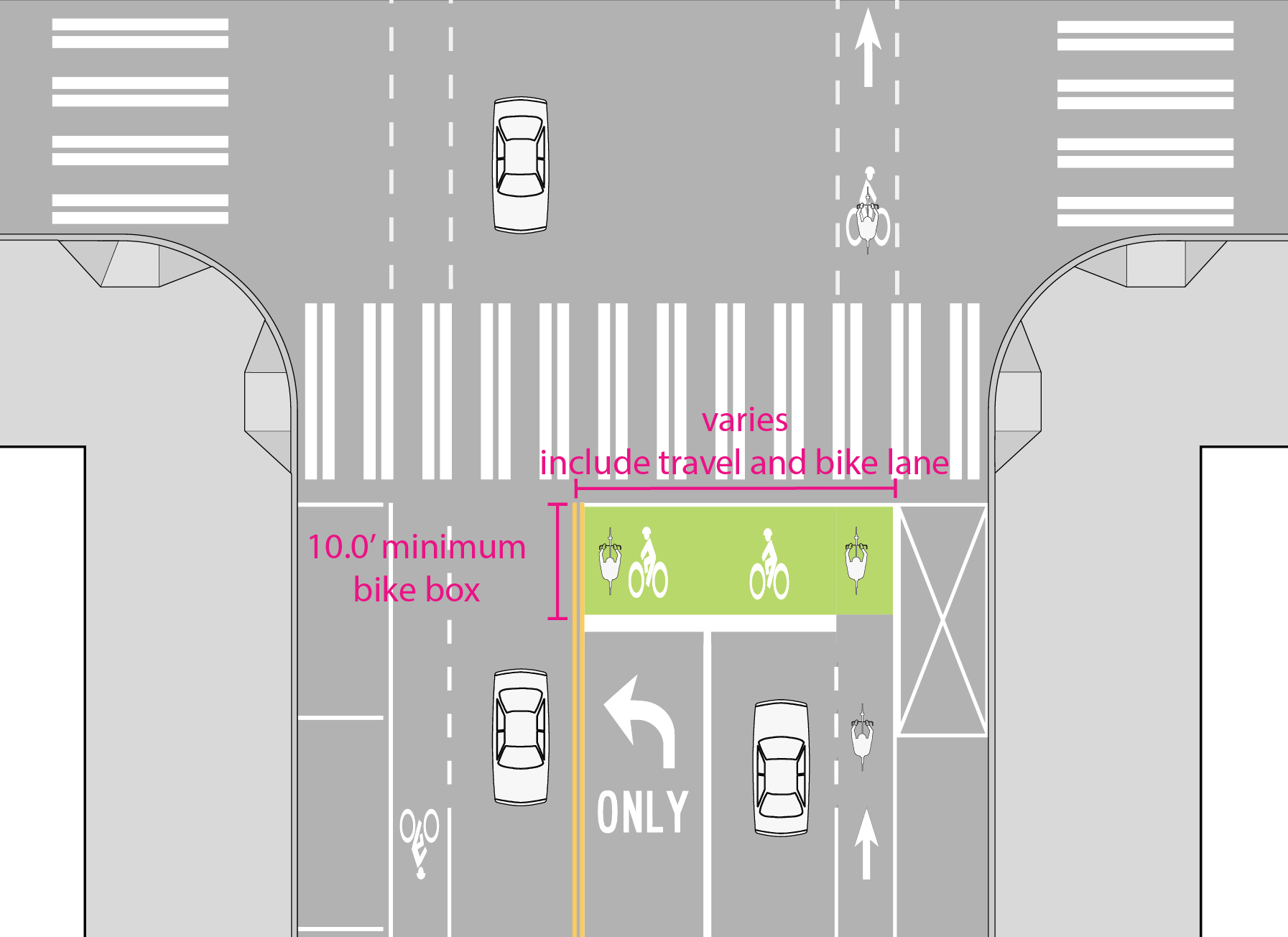
Bicycle Box
A designated area at the head of a traffic lane at a signalized intersection. A bicycle box provides a head start at the onset of green, reducing the potential for right hook collisions.
Design Standards
- Bicycle box should be 10 feet minimum depth, and the full width of bicycle lane (if present) and adjacent general purpose travel lane together.
- Bike boxes may extend across a left-turn lane lane to facilitate bicycle left turn movements, but generally should not be extended across more than one through lane.
- Must include stop lines for motor vehicles behind the bike box and include “Stop Here on Red” sign (R10-6A)
- Pavement markings within box are advisable. “No Turn on Red” restrictions (R10-11) are mandatory.
- Green pavement markings shall be used within the bike box and the first 25-50 feet of the lead-in approach/ingress lane to enhance visibility.
Design Guidance
- The bicycle box should be located to minimize the likelihood of motor vehicle encroachment from turning vehicles. This may require the stop line be recessed further from the crosswalk in some locations.
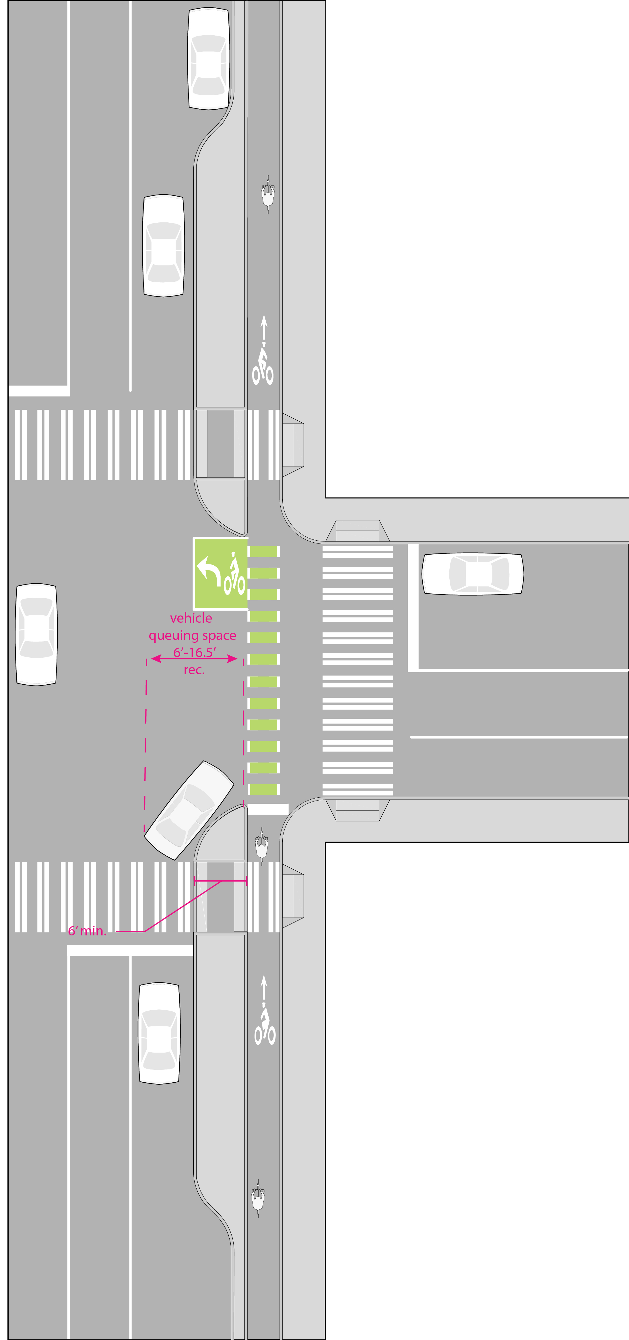
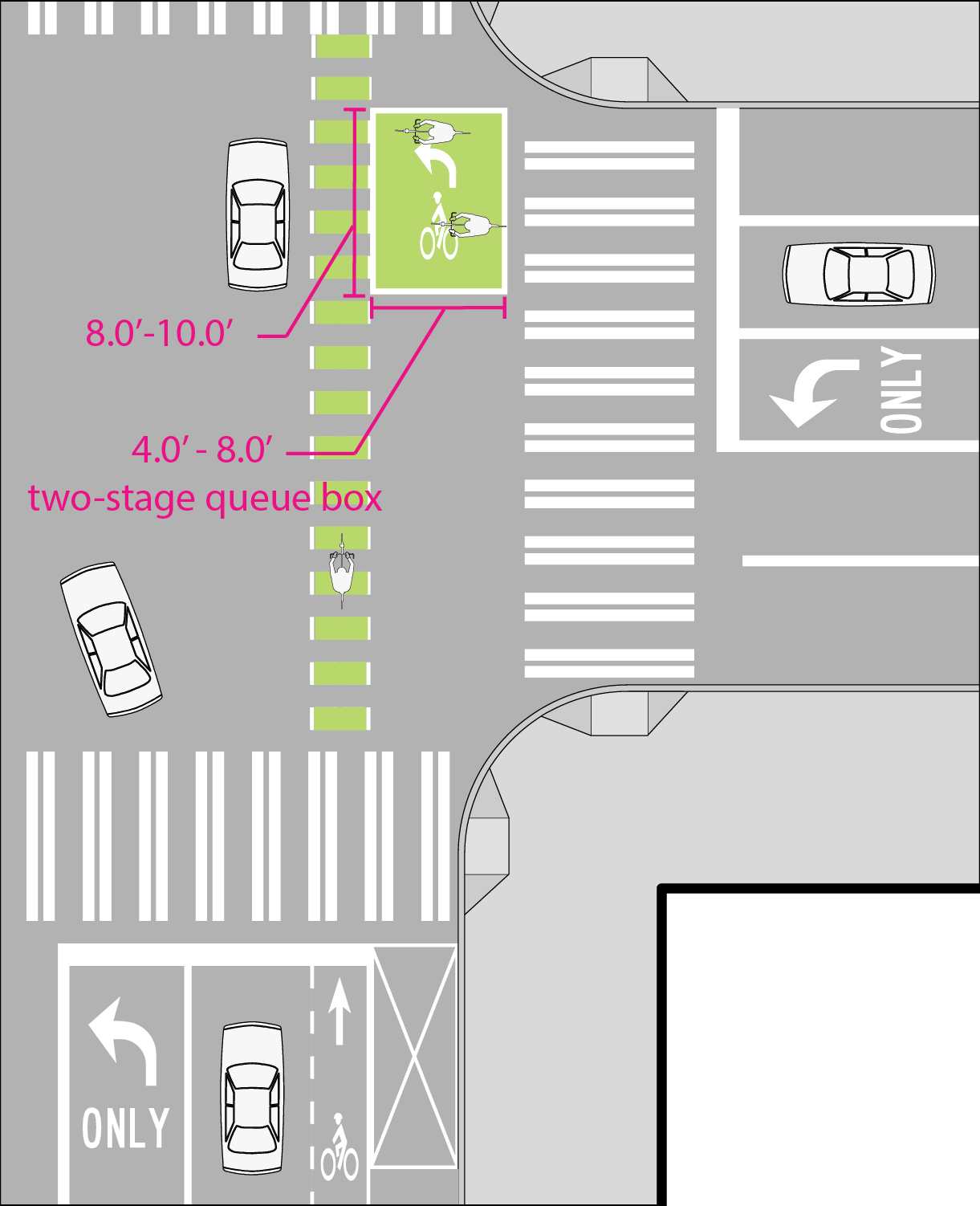
Two-stage Turn Queue Box
A two-stage turn queue box designates a space for bicyclists to wait while performing a two-stage turn across a street at an intersection.
Design Standards
The queuing area should be placed to provide good visibility (see Design Guidance at top of page for stopping site distance equation) of bicyclists by motorists. Two-stage turn queue box dimensions and placement will vary based on the roadway operating conditions, the presence or absence of a parking lane, the type of bicycle facilities present, traffic volumes and speeds and available roadway space.
The box should consist of a green box outlined with solid white lines supplemented with a bicycle symbol. A turn arrow should be used to emphasize the crossing direction.
The queuing area should be 4 to 8 feet deep (measured in the longitudinal direction of bicycles waiting in the box). Deeper queuing areas allow for longer bikes to queue without encroaching into the crosswalk or crossbike. The width of the box should be 8 to 10 feet.
The turn box may be placed in a variety of locations, but must be in a protected area, out of the stream of traffic (e.g. at the tail end of a parking lane or a median island). The turn box should be placed on the intersection side of a crosswalk to eliminate potential conflicts with pedestrians in the crossing. At T- or off-set intersections a turn queue box may be placed in a “jug-handle” configuration within a sidewalk or within the parking lane. Dashed bicycle lane extension markings may be used to indicate the path of travel across the intersection. “No Turn on Red” (R10-11) restrictions should be used to prevent vehicles from entering the queuing area.
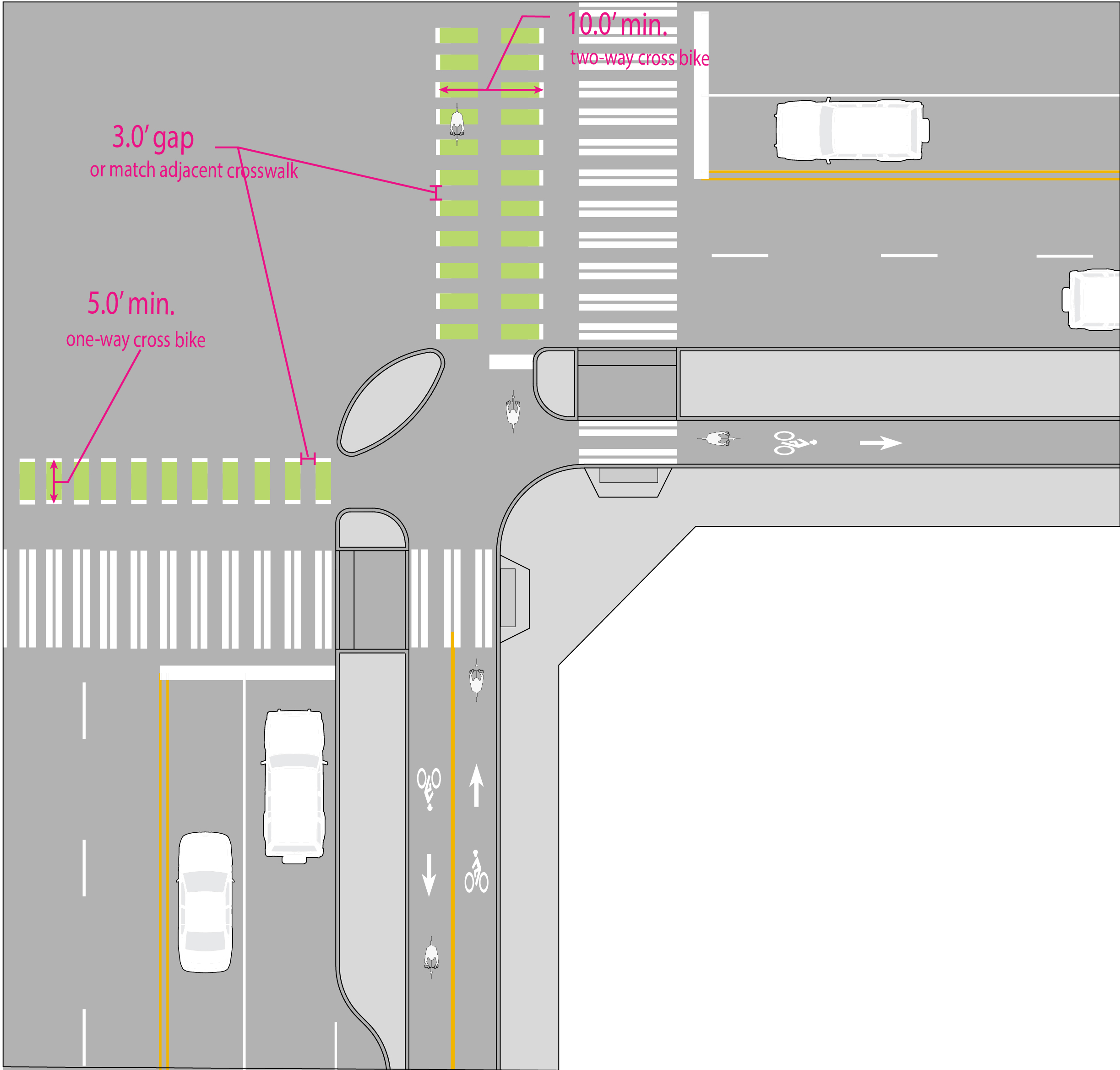
Cross Bicycle Intersection Markings (“cross bikes”)
Bicycle lane extension markings through an intersection. The extensions increase awareness of bicyclists to motorists and guides bicyclists on a direct path through the intersection. Cross bikes can also be used at locations where off-street pathways cross roads, particularly in locations that include separate parallel pedestrian facilities with pedestrian crosswalks.
Installation of crossbikes for un-buffered bike lanes will be based on the following factors when two or more of these factors indicate that a crossbike may be appropriate:
- Turning volumes across the bike lane
- Pedestrian volumes parallel to bike lane (peak hour)
- Collision history
- Downhill grade 5% grade or multi-block approach at >3%
- Sight distance
Design Standards
- Cross bicycle intersection markings, aka “cross bikes” may be marked with dotted bicycle lane line extensions.
- A one way crossing should be 5 feet minimum width; two-way 10 feet minimum width. Dotted line extensions may be supplemented with bicycle lane symbols or green pavement markings.
- Markings should be 2 feet in depth (direction of bicycle travel). The gap or spacing between markings should match adjacent crosswalk markings. Where there is not an adjacent marked crosswalk markings should be spaced with a 3 foot gap.
Design Guidance
- Placement of bicycle lane markings should factor in paths of crossing motor vehicle wheels to minimize wear.
- Intersection crossing markings are particularly useful where the bicycle travel path through the intersection is unusual (e.g. diagonal crossing or from an off-street facility) or needed to separate conflicts.
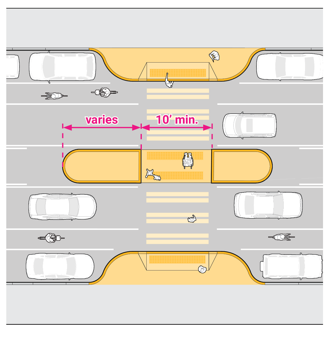
Median Diverter Island and Standard Median or Crossing Islands
Protected spaces in the center of the street to facilitate bike and pedestrian crossings; may also divert vehicular traffic by preventing through movement. Bikes and pedestrians can navigate one direction of traffic at a time.
Design Standards
- Islands should be 8 to 10 feet wide to accommodate multiple users, bicycles with trailers, etc.
- Minimum island width is 6 feet.
- The length of islands may vary.
- A cut-through design is preferred over curb ramps. Minimum cut-through width is 6 feet; the desirable width is the width of the crosswalk.
- Detectable warnings should be used on each approach to the roadway.
- If the width of an individual cut-through is 8 feet or greater, a flexible post should be placed in the center of the cut-through in order to prevent motor vehicles from using the cut-through. The flexible post should meet the standards outlined above.
Design Guidance
Islands may contain landscaping, but it must not exceed 24 inches in height at full maturity so as not to impact visibility. At uncontrolled intersections and midblock crossings, additional crossing treatments are recommended.
Locations where trucks, buses or emergency response vehicles are frequent may require a modified island design or not be appropriate for this treatment.
Curb Bulbs
Help position bicyclists closer to the cross street centerline to improve visibility and encourage motorists to yield to pedestrians. See the Pedestrian Crossing section for additional design guidance for curb bulbs.
Design Standards
- Preferred width 6 feet where parking lanes are present.
- It is desirable to maintain bike lane width through the curb bulb area. The gutter line of curb bulb shall not be factored into bike lane width.
- Curb bulb placement shall not preclude planned bicycle facilities. See the Planning Analysis Coordination Tool (PACT) to track projects in the right-of-way.
Offset Street Connection
Offset streets can be challenging for bicyclists to navigate. Common configurations include bicycle lane offset street connection, cycle track offset street connection, bicycle center turn lane, or two-stage boxes.
Design Guidance
Design will be context dependent and will vary significantly depending on the direction of offset. Consider wayfinding, turn lanes or pavement markings to improve bicycle connections.
On streets with heavier volumes and higher speeds, design treatments may include two-stage left turn boxes (for offset streets to the right of one another), placed in the through-street parking lane, along with a cross walk or crossing island. Other options include a pair of one-way protected bike lanes, or a two-way protected bike lane, crossing island, and contra-flow bike lanes.
For signalized offset streets to the left of one another, dedicated bicycle left turn lanes on the offset streets may be appropriate. In this case an LBI signal phase should be considered to allow the left-turning bicyclists to move to the right side of the through street as part of their left-turn maneuver.
The selection of treatment should also consider the neighboring land uses which might facilitate a predominant type of bicyclist that will use the intersection. Take into account the comfort level of maneuvering in the roadway and the amount of delay the treatment imposes on bicyclists.
