3.5 Structures Within the Right-of-Way

City-owned structures are structures in the City’s right-of-way installed to benefit the general public, built according to approved plans and specifications, which then are owned and maintained by the appropriate public entity such as: Department of Transportation; Parks and Recreation; Public Utilities; Fleets and Facilities or other public agencies. The primary types of structures are retaining walls, bridges, stairways and other transportation structures. All design elements shall conform to this manual. In addition, each public facility owner may have a specific acceptance policy by which the structural types, design details and construction practice are evaluated prior to approval.
Privately owned structures are installed with the development of private property and are maintained by the adjacent property owner. These structures, such as retaining wall systems, balconies, bay windows, or roof overhangs, require a Public Space permit and an indemnity agreement (or insurance). The owner will be responsible for the renewal costs of the Public Space Permit.
All proposed structures, shall require the approval of the Director of Transportation prior to the issuance of the construction permits. Submittal for approval shall include stamped plans and calculations, specifications, relevant survey and geotechnical information used for the design.
Links to Standard Plans and Specifications
Standard Plan 141: Rock Facing
Standard Plan 440a and 440b: Cement Concrete Stairway & Handrail
Standard Plan 441: Cement Concrete Steps
Standard Plan 442: Steel Pipe Handrail
Standard Plan 443: Pedestrian Railing
Standard Plan 800: Support Wall
Standard Plan 801: Curb Wall
Design Criteria
Wall Location
Cuts and fills along the edge or end of a roadway occur when the existing ground and proposed elevations differ. A retaining wall system is required if the elevation difference cannot be maintained with a maximum allowable ground slope per design standards. The intent of the wall limit shall be clearly defined on the drawings, including details for the wall ends. Private walls in the right-of-way should be minimized to the greatest extent possible.
Barriers, railings or fencing at the top of these walls may be required to provide safer passage. This requirement will be determined by the Transportation Operations Division of the Department of Transportation.
Design Standards
All design shall be performed by or under the direction of a professional structural engineer.
The following design standards shall be used:
- City of Seattle Right-of-Way Improvements Manual
- City of Seattle Standard Plans for Municipal Construction
- Washington State Department of Transportation (WSDOT) Design Manual
- WSDOT Bridge Standards
- AASHTO LRFD Bridge Design Specifications, 8th edition September 2017
- International Building Code (case by case basis).

Wall Types and Details
Erosion facing/non-structural walls: When the soil is determined to be stable under static conditions by a geotechnical engineer, the erosion facing wall, such as rock facing or decorative stackable masonry blocks may be used. These are considered non-structural walls. Refer to Rock Facing Wall Standard plans. The maximum allowable height for this wall system is 8 feet.
Alternate erosion facing may include stackable masonry blocks, jut matting, etc. Any near vertical erosion facing needs to meet the same slope and clearance criteria as rock facing and requires the approval of the Director of Transportation.
Structural Walls: When soil is unstable under static conditions, a structural wall is required to support the soil permanently. SDOT accepts both the standard and non-standard structural wall types. For proposed structures that are non-standard and lack the long-term performance history, pre-approval of the concept is required before design work should proceed.
An example of a non-standard wall is structural soil (geoweb soil wrap) wall. This wall system may be designed where no utilities or excavations would be anticipated. Permission to use these types of walls is rare, due to future utility uses and the no-dig zone space required for the soil mass.
Proposed City-owned and maintained structures require the approval of the Roadway Structures group of the Department of Transportation.
General Requirements:
- If a retaining wall is not designed to resist hydrostatic pressure, install a 6-inch diameter subsurface drain and 3-inch diameter PVC weep holes spaced 12 feet apart. The weep hole shall be placed 6 inches above the finished grade at the toe of the wall, per City of Seattle Standard Plans. The subsurface drain shall be tied into the City drain systems, as approved by SPU. Refer to the Standard Specifications for Weep Hole Detailing.
- If a retaining wall is designed on top of an existing retaining wall, the new retaining wall should be designed with the assumption that the lower wall is not contributing to the lateral support to the slope below the newly designed retaining wall unless approved by Roadway Structures. Similarly, if the wall is designed at the toe of a slope below an existing retaining wall, the toe wall shall include the surcharge of the existing wall unless approved by Roadway Structures. (See Standard Plans 800 and 801)
- Wall details that are water and debris traps should be avoided.
- Pedestrian guardrail openings shall not exceed 4 inches wide and the general layout shall discourage climbing activity.
- Private and public retaining walls shall not be built integrally. Total structural isolation is required for adjacent walls.
- Concrete walls that are prone to graffiti shall be coated with a moisture barrier and anti-graffiti paint.
Types of Structures Common to the City:
Reinforced Concrete Cantilevered Retaining Walls: Standard WSDOT cantilever reinforced concrete retaining wall design is acceptable. For walls longer than 30 feet, those must have expansion joints at a maximum of 24 foot spacing.
Soldier pile walls: Soldier pile walls are applicable when the soil types are unsuitable for other wall systems and where the right-of-way is unavailable for a standard cantilever retaining wall. This wall system shall have a reinforced concrete face and may be constructed with shotcrete or cast-in-place methods. Precast concrete panels are also acceptable on case by case basis. Timber laggings are not considers as a permanent structure. Weep holes and drainage shall be provided behind the wall. Unless enclosed by structural concrete, steel wide-flange piles should be coated with zinc rich primer and coals tar epoxy per City standard Specifications from the top of the wall to a minimum of 2 feet below the bottom of the lowest lagging.
Stairways: Stairways in public right-of-way shall be designed according to Seattle Standard Plans 440a and 440b. Alterations to existing stairways that directly serve a City of Seattle public facility require a review of feasibility to provide an accessible vertical access or an alternate accessible route if one does not already exist. Pedestrian lighting shall be provided for stairways. Consider the incorporation of runnels to accommodate people walking with bicycles.
Handrails and pedestrian rails: Railings shall be designated as “handrails” or “pedestrian rails” and their usage shall be as determined by the figure below:
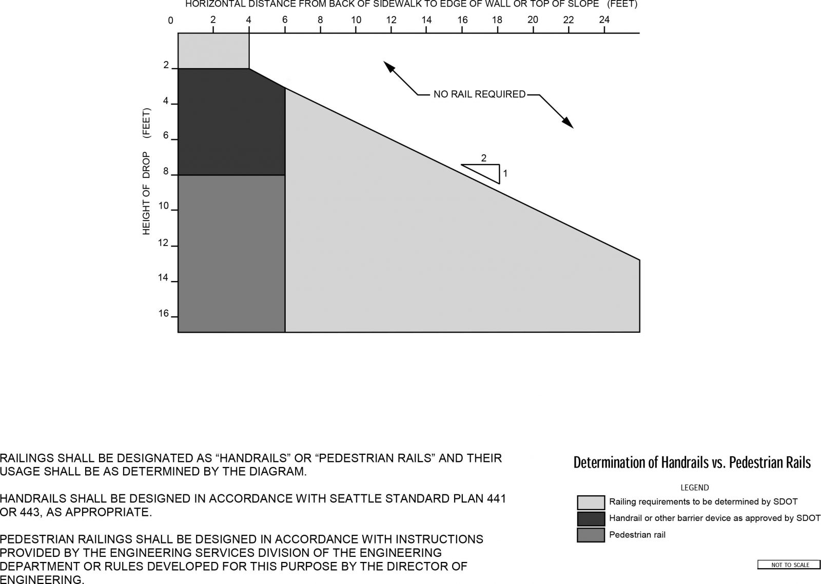
Handrails shall be designed in accordance with Standard Plan 442 or 443, as appropriate.
Pedestrian rails shall be designed in accordance with criteria established by the SDOT Director, in compliance with guard requirement of the International Building Code (IBC), meaning that they shall have a maximum spacing of 4” for vertical elements of the railing.
Traffic barriers: Vehicular railings on bridges shall be designed in accordance with AASHTO standards. Vehicular railings on retaining walls shall be designed in accordance with AASHTO standards unless otherwise approved by the SDOT Director. Vehicular guardrails on approaches to structures shall be designed according to Washington State Department of Transportation standards. For guardrails not on structures, the SDOT Director will determine the type of guardrail required.
Pedestrian overpasses / underpasses and skybridges: Pedestrian overpasses and underpasses typically span a transportation right-of-way and provide a connection between destinations that have a high volume of pedestrian use. Pedestrian overpasses shall be designed in accordance with criteria established by the SDOT Director. Skybridge permit policies are defined in the SMC section 15.64 Skybridge Permits. SDOT requires AASHTO LRFD standard designs over the street provided it does not conflict with the applicable code to the building where the bridge is bearing on.
Areaways: Use the IBC for structural design with 250 lbs/sf live load for sidewalk top or HS20 whichever governs. Include curb ramps in the surface of the areaway to mimic Standard Plan 422 at intersections (including “T” intersections).
Bridges: Bridges shall be designed in accordance with AASHTO LRFD Bridge Design Specifications.
Other structures: Sign support structures, strain poles and foundations, mast arm poles and foundations, and streetlight poles shall be designed in accordance with 2013 AASHTO Standard Specifications for Structural Supports for Highway Signs, Luminaires, and Traffic Signals (6th Edition). Considerations shall be made by the designer and pole manufacturer that poles designs are appropriate for the urban environment. Dimensions for pole sizes shall be provided according to the City of Seattle Standard Plans. Deviations in these dimensions will be considered on an individual basis. If additional future unallocated capacity and overly conservative assumptions are made in the calculation of pole strength these deviations will not be granted.
As described in City of Seattle Standard Plans 541 and 562, strain and mast arm signal pole foundations will need to be designed based on the pole-specific loading and site-specific soil conditions. The following design criteria shall apply:
Basic Wind Speed: 85 mph
Importance Factor: 1.0
Design Life: 50 years
The pole foundation depth shall be determined based on the soil zone that the pole is located in. Three generalized soil zones have been established:
- Higher Strength Soil Zone: standard foundation depths for mast arm poles provided in Table 1.
- Lower Strength Soil Zone: standard foundation depths for mast arm poles provided in Table 1.
- Site-Specific Study Zone: requires design using soil properties developed by a site-specific geotechnical evaluation.
Foundation depths for strain poles shall be based on pole-specific loading and the soil properties from the applicable soil zone. See Figure S1 for an example of items on a 60 ft mast arm.
A summary of the design procedure for mast arm pole foundations is as follows:
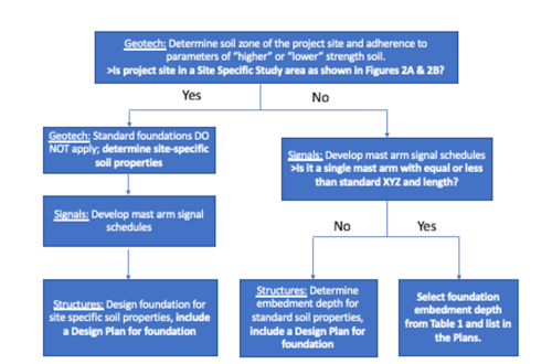
As a guide, the Design Zones Map in Figures S2 and S3 can be referenced for preliminary design purposes. The design zone should be established during the scoping phase of the project. A qualified geotechnical engineer shall verify that soil conditions at the proposed location meet the minimum criteria for the assumed design soil zone as indicated in Tables 2 and 3.
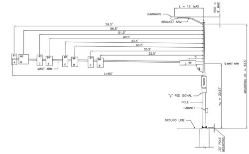
Figure S1. Items on a 60 Foot Mast arm
Table 1: Mast Arm Pole Foundation Embedment Depths
| Maximum Mast Arm Length (see Note 1) | Maximum XYZ (ft3) (See Notes 1,2) | Foundation Embedment Depth “D” (See Note 3) | |
| Soil Type (See Note 4) | |||
| Low Strength | High Strength | ||
| 20′-0″ | 610 | 11′-0″ | 9′-6″ |
| 30′-0″ | 1130 | 13′-0″ | 10′-0″ |
| 40′-0″ | 1610 | 16′-0″ | 10′-6″ |
| 50′-0″ | 2100 | 19′-6″ | 12′-0″ |
| 60′-0″ | 3090 | 25′-0″ | 15′-6″ |
Note 1: Embedment Depth “D” must satisfy both mast arm length and XYZ; use whichever controls.
Note 2: XYZ values are determined by multiplying the Effective Projected Area of the luminaire and each mounted appurtenance (X*Y) by the offset of the item to the vertical centerline of the pole (Z) and determining the sum of X*Y*Z for all items. Effective Projected Areas are in accordance with Section 3.9.1 of the 2013 AASHTO Standard Specifications for Structural Supports for Highway Signs, Luminaires, and Traffic Signals (6th Edition) and include the Drag Coefficient Cd.
Note 3: Embedment depths apply for flat ground only.
Note 4: See Figures S2 and S3 for the Foundation Design Soil Zone Map indicating soil type regions.
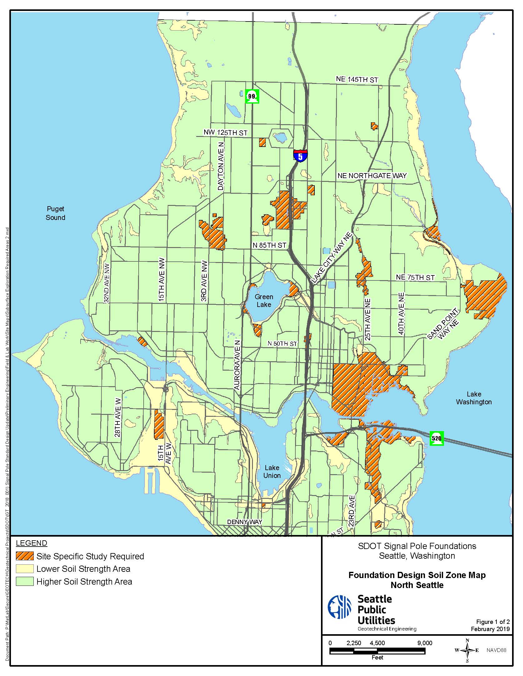
Figure S2. Foundation Design Soil Zone Map, North Seattle
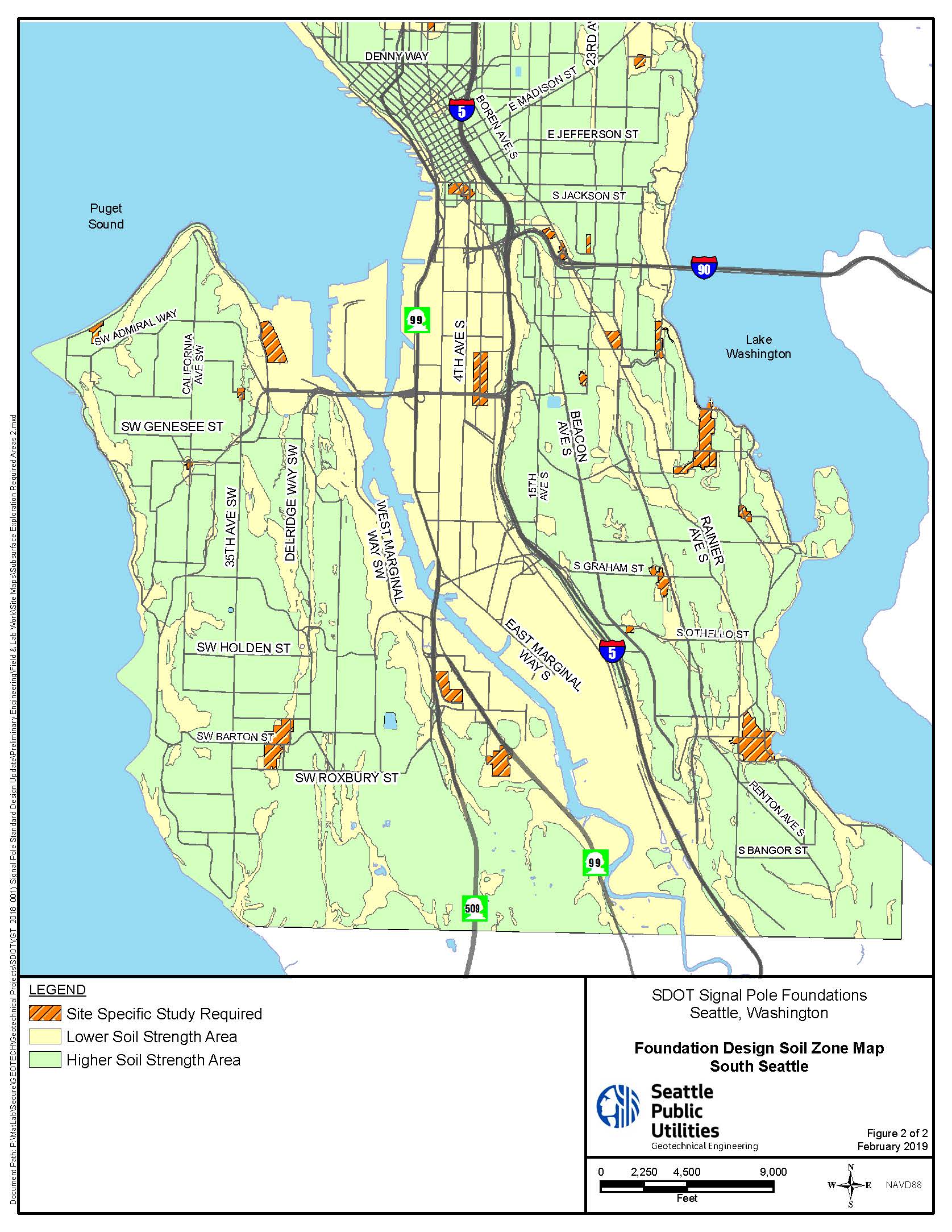
Table 2: General Geotechnical Design Parameters
| Soil Type | Passive Earth Pressure Coefficient (Kp)* | Effective Unit Weight Below Groundwater (γ) (pcf) | Friction Angle (degrees) |
| Higher Strength | 4.14 | 57.6 | 30 |
| Lower Strength | 3.30 | 47.6 | 26 |
* Values apply for flat ground; passive earth pressure values should be provided by a geotechnical engineer if the ground is sloped. Do not use 33 percent increase in allowable strength for Group Loads II and III as shown in Table 3.4-1 of the AASHTO Standard Specifications. A minimum factor of safety of 2.86 shall be applied to the loading.
Table 3: Geotechnical Design Parameters for Torsional Resistance
| Depth Below Ground Surface (ft) | Unfactored Unit Torsional Resistance (psf)** | |
| Higher Strength Soil | Lower Strength Soil | |
| 0 to 5 | 210 | 100 |
| 5 to 10 | 520 | 240 |
| 10 to 15 | 670 | 330 |
| 15 to 20 | 760 | 380 |
| 20 to 25 | 840 | 420 |
**Values apply for concrete cast directly against soil and a groundwater table a minimum of 5 ft below grade. If a permanent steel casing is used, a reduction factor of 0.65 shall be applied to the torsional resistance values. A minimum factor of safety of 1.25 shall be applied to the loading.
Construction Specifications
Slope stability shall be maintained at all times during the constructions of the wall system. Common methods used include temporary cut slopes, temporary shoring or temporary shotcrete.
Submittal of the construction specifications are required for the mechanically stabilized earth (MSE) wall.
Permission: During construction access rights from adjacent property owners may be needed. A negotiation for these rights by the developer needs to begin as soon as the need is discovered. SDOT will provide the needed document for signature by the affected property owner giving the right to enter private property for the scope of the construction and maintenance of the project.
Ownership/Maintenance Acceptance: Acceptance of privately built retaining walls that will be maintained or owned permanently by SDOT require the following prior to formal acceptance:
- As-built shop drawings and plans in Mylar and are filed in the City’s Record Center, (SPU’s Record Vault).
Reduced size as-built final design calculations with the Structural Engineer’s stamp and signature as well as the geotechnical report submitted to Roadway Structure’s staff and all punch list items are completed to the satisfaction of the inspector.
Traffic and Curb Signs in the Right-of-Way
Design Standards
- Signs within the street right-of-way are primarily installed by Parking Management and Transportation Operations.
- Signs must follow federal and state regulations. Curb space is legally defined by signs but may also be supplemented by paint or other treatments.
- Signs shall not be placed within the pedestrian clear zone.
The Manual on Uniform Traffic Control Devices, or MUTCD, defines the standards used by road managers nationwide to install and maintain traffic control devices on all public streets, highways, bikeways, and private roads open to public traffic. Sign placement is informed by the MUTCD, but engineering staff also take into account the specific conditions on that particular block – such things as sight distances, curves, slopes and vegetation – when locating a sign.
Curb Use Designation: Signs defining areas where curb use is restricted to specific vehicle types (eg. Law enforcement) or specific uses (eg commercial load zones or passenger load zones) shall be placed at the downstream end (head of the zone) of the special use area. For longer zones (>40’), supplemental signs may be valuable to provide clarity to users. Curb use designation signs are typically installed on 5’ posts so that the driver of the vehicle can read the sign while sitting in the car. Usually installed in the amenity/furniture zone.
Design Guidance
Sign placement is based on federal and state regulations, but is also dependent on legibility with potential conflicts with trees, utilities, other signs, or channelization. Signs with less stringent federal regulations like midblock no parking signs can be placed depending on best visibility. When appropriate, update existing signs during street improvement projects with most up-to-date signs found in the Hansen sign catalog.
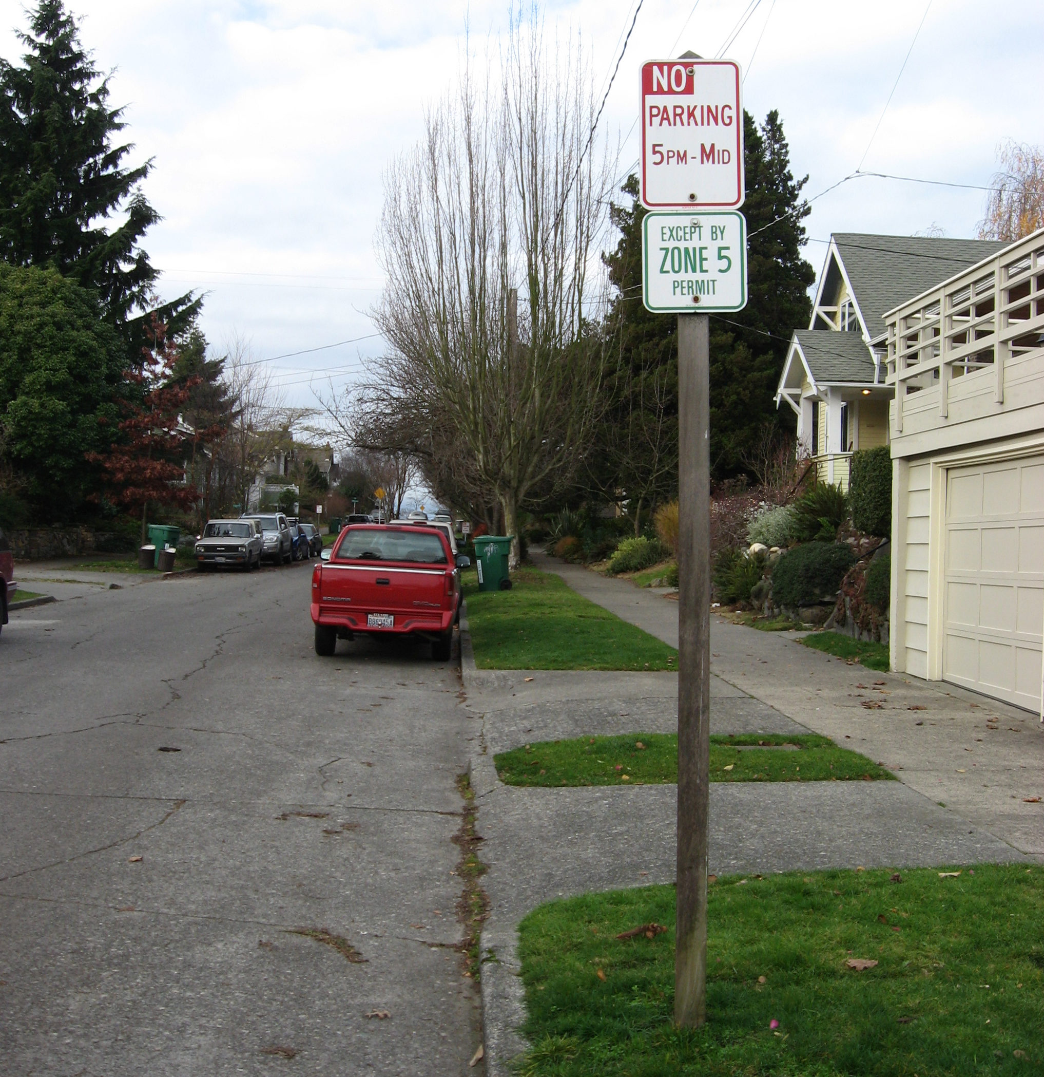
NO PARKING sign spacing: No Parking signs should be spaced on a block face at around 100 foot increments or as unobscured visibility allows.
Sign sight distance: In a complex urban environment, providing unobstructed sight distance to traffic signs can be a challenge, and it is important that designers consider existing signing, visual obstructions, and the potential for exacerbating visual clutter. To be effective, signing must provide both adequate visibility and legibility to clearly convey the necessary message. New signs should be located to take into account conditions when installed and expected future conditions including tree growth, parked vehicles and impacts to the pedestrian zone.
Sign placement must be compliant with MUTCD and ADA standards as well as the clearance guidance found elsewhere in the ROWIM. Newly installed signs must be located to provide the following minimum unobstructed sight distances from each approaching lane based on the speed limit of the roadway that they are installed on:
| Speed Limit | Sign sight distance |
| 20 | 100 ft |
| 25 | 135 ft |
| 30 | 170 ft |
| 35 | 215 ft |
| 40 | 265 ft |
Sign height: Signs in areas with high pedestrian volumes should have the bottom of the lowest sign 7’ from the ground for pedestrian clearance. Default to a 10’ sign (TS10) when there are no visual impairments. Curb use designation signs are typically installed on 5’ posts so that the driver of the vehicle can read the sign while sitting in the car.