3.11 Freight
The City of Seattle Freight Master Plan (FMP) contains an updated city freight network in order to improve freight mobility and to direct future investments. The design standards and guidance in this section is intended to be used in the development of roadway improvement projects to better understand how truck movements can affect street design and streetscape features.
For additional design guidance for freight see the FMP Appendix C. Note: The Seattle Department of Transportation does not support truck aprons as a standard design practice.
Updated Freight Network
While trucks are allowed on all arterials in the city, they are encouraged to use certain streets because of their designation in the freight network and the land uses they serve. The FMP has identified a network of roadways that especially serve truck mobility and connectivity and use the following freight street classifications:
- Limited Access Facility
- Major Truck Street
- Minor Truck Street
- First/Last Mile Connector
A description of the four freight street classifications is shown below in relationship with the assigned street types:
|
Classification |
Street Type |
Function |
Roadway type |
Truck volumes |
Design objective |
|
Limited Access Facility* |
N/A |
Serves long-distance through trips between the city and the rest of the region |
Highway |
All |
Design to be limited access facilities and to standards that facilitate all types of trucks |
|
Major Truck Street
|
Serves through trips between Manufacturing and Industrial Centers, intermodal facilities, urban centers/villages, and the regional system |
Minor arterial or higher |
500+ trucks per day |
Design to accommodate all truck types, as practicable |
|
|
Located in Manufacturing and Industrial Centers often connecting to Urban Center Connectors |
Minor arterial or higher |
500+ trucks per day |
Design to facilitate the movement of all truck types and over-dimensional loads, as practicable |
||
| Located within urban villages or centers. |
Principal arterial |
Designed to accommodate large trucks that move through urban villages or centers. | |||
|
Located in the downtown core and serves trips through the regional system |
Principal arterial |
Designed to accommodate large trucks that move through urban villages or centers. | |||
|
Minor Truck Street
|
Serves through trips between Manufacturing and Industrial Centers, intermodal facilities, urban centers/villages, and the regional system |
Minor arterial or higher |
Design to accommodate all truck types, as practicable |
||
|
Serves both through and to/from trips connecting urban centers/villages and commercial districts; provides secondary connections to major truck streets |
Principal or collector arterial |
500+ trucks per day |
Design to accommodate truck needs in balance with other modal needs of the street |
||
| Located within urban villages or centers. |
Minor or collector arterial |
||||
|
Located in the downtown core and serves trips through the regional system |
Minor or collector arterial | ||||
| Serves as local neighborhood connections but is not part of the major transit or freight network | Minor or collector arterial | ||||
| First/Last Mile Connector |
Serves trips to/from industrial facilities, within the Manufacturing and Industrial Centers |
Collector or Minor arterial |
250+ trucks per day |
Design to facilitate the movement of all truck types and over-dimensional loads, as practicable |
Table 1 – Freight Network Classifications
*Design typically determined by the Washington State Department of Transportation (WSDOT)
Route Information
The City maintains online information for freight mobility which includes:
- Freight Mobility Network map
- Permitting requirements for over-legal loads
- Weight restrictions on City-owned bridges
- Traveler information website with real-time traffic impact maps
- City and state traffic cameras
The City also maintains a network of dynamic message signs to provide information to people driving on the road. Additional policies and programs will be added to the Freight Master Plan that promote the development of technologies to benefit freight movement through mapping, dynamic message signs, and mobile applications, and compiling these resources into a central location.

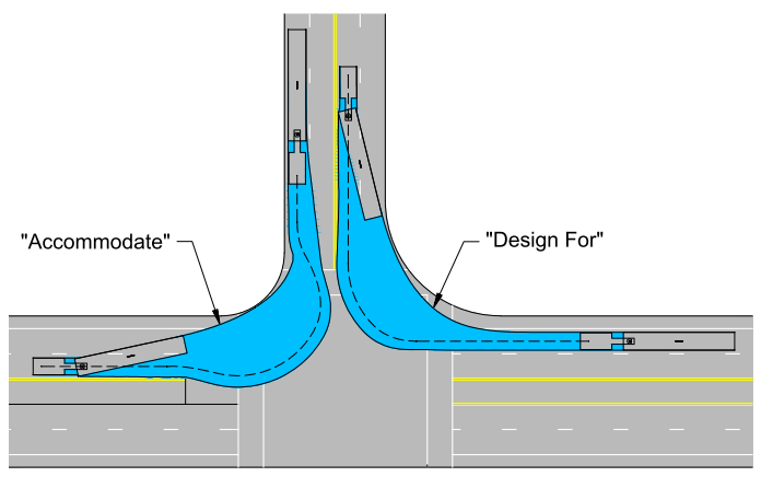
“Design for” versus “Accommodate”
The Freight Master Plan outlines the difference between “design for” versus “accommodate” when designing a project. The plan recognizes that both “design for” and “accommodate” have their place to enable safe mobility for all people traveling through Seattle’s constrained urban environment. The plan states:
“Accommodating for a vehicle allows encroachment of other lanes, shoulders, or other elements to complete the required maneuver. Designing for a vehicle does not require encroachment onto those elements. Typically, an intersection turn movement is considered “designed for” if the design vehicle is allowed to encroach on the lane adjacent to the typical receiving lane for the turn movement (right lane for right turns), provided that encroachment is not into opposing traffic”.
Trucks should not cross the centerline of the roadway into opposing traffic with few exceptions, for example turning onto a minor street with stop sign controls with limited expected traffic. At signalized intersections, no encroachment into opposing traffic should occur past the stop bar for the opposing traffic (i.e., a recessed stop bar may be used to allow for this movement without presenting a conflict with queuing vehicles).
Truck size and type are important factors when planning and designing a project, especially at intersections. For a typical passenger vehicle, the path followed by the rear wheels is almost the same as that of the front wheels. With larger vehicles, the swept area becomes much larger as the inside rear wheels track substantially inside of the path of the front wheels. This becomes the most critical factor in sizing the intersection.
All streets in this design manual are “designed for” the standard design vehicle, an SU-30 with a 42′ turning radius, with the exception of non-arterials which “accommodate” the standard design vehicle, and arterials on the Freight network. Arterials on the Freight network are “designed for” the common large trucks, as defined by AASHTO in Figure BW below.
Types of Trucks (Design Vehicles)
Trucks come in a variety of sizes. These sizes and overall dimensions are dictated by the goods or materials being transported. Trucks typically range from 8.5- to 10.0-feet wide, and with permits can be even wider. Mirrors extend beyond this envelope, typically adding another 12 inches to either side of the vehicle.
The American Association of State Highway and Transportation Officials (AASHTO) has classified the most common sized trucks on United States roadways based either on the overall length of the vehicle (buses and single unit trucks) or vehicle wheel base (tractor-trailers). The classifications include:
- SU-30: 30.0-foot, single unit vehicles typical of most local delivery vehicles (this is the ROWIM’s standard design vehicle on streets not included in the Freight Network)
- WB-40 and WB-50: small tractor trailers with wheelbases in the 40.0-foot and 50.0-foot range
- WB-67: 67-foot wheelbase long haul trucks, sometimes called the interstate design vehicle that has an overall length on the order of 74.0-feet.
Figure BW shows the typical dimensions of the most commonly used AASHTO design vehicles. Additional information on these and other design vehicles can be found in the AASHTO Policy on Geometric Design of Highways and Streets. See the Intersection section for more information on design vehicles for Streets Illustrated.

Over-legal Trucks (Weight and Size)
These vehicles and loads exceed the maximum height, weight, width, and/or length, specified by state law. All oversized vehicles and loads traveling within Seattle must obtain a permit to operate. City law allows SDOT to issue these permits. Over-legal loads are an important form of freight movement in Seattle. These movements include frequent loads like construction cranes, to less frequent movements like public art pieces. The over-legal routes in the city provide basic north-south or east-west mobility for trucks that are over-height, over-width, over-length, or over-weight. Trucks falling into this special category are larger than 8.5-feet wide, 14.0-feet high, and/or are carrying loads exceeding 80,000 pounds. They require a special permit to travel throughout the city, and typically require an escort. Seattle has an established network of over-legal streets predating the establishment of the interstate system that is used to facilitate the movement of goods in and out of Seattle.
To meet the needs for over-legal vehicles, the City has typically required a 20.0-foot wide by 20.0-foot tall clearance envelope for streets on the over-legal network. During project development SDOT staff coordinates with other divisions to preserve the over-legal dimension envelope needed to transport loads that over dimension and weight through various city streets. Intersections where such trucks are expected to turn should also be examined to accommodate the turning of these vehicles, particularly at junctions with state highways and interstates.
Design Standards
This section identifies design standards that can be used to design for and accommodate trucks on Seattle’s freight network. Truck characteristics that most influence the design of roads and other transportation facilities are weight, dimensions and turning radius. Some of the practices herein may also have applicability to any street in Seattle where large truck movements need to be accommodated.

Coordination with Freight Network
Seattle’s Freight Master Plan has classified a number of streets as part of the freight network with a level of classification based on the characteristics of the specified truck traffic including volume, land use, origin/destination, connectivity, etc. The most common needs for truck mobility include:
- Vertical clearance: Freeways and state highways generally require 16.5-feet minimum of vertical clearance to provide for the widest range of freight, including oversized loads as well as national defense. Seattle’s Major Truck Streets and First/Last Mile Connectors provide a similar function. Lesser heights can be allowed on Minor Truck Streets, but adjusted as necessary if a street is identified for over-legal vehicles. See clearance section for design standards.
- Weight allowance: Limited Access Facilities, Major Truck Streets, and First/Last Mile Connectors will routinely carry high volumes of fully loaded trucks, and may allow over-weight trucks by permit. Truck streets classified at as Minor Truck Streets will typically not have the consistent combination of these elements. Bridge and pavement design should follow AASHTO or other applicable guidance and be based on anticipated truck traffic. Please refer to the Heavy Haul Network for routes that are designated to accommodate over-weight.
- Curb radius: Provide for turning of the design vehicle determined appropriate through preliminary project development and design. Special attention should be paid where streets on the freight network intersect, and businesses along a corridor have access needs where frequent turning movements are made. The table below lists the standard curb radius per street type and specifically for major and minor truck streets. As context requires, deviations from these standards are considered on a case-by-case basis.
|
Neighborhood Yield Streets Intersecting |
10 feet |
|
|
All other Street Types, except Freight network |
20 feet |
|
|
Minor –Minor Truck Streets Intersecting |
25 feet |
|
|
Major –Major Truck and/or FTN** Streets |
30 feet |
|
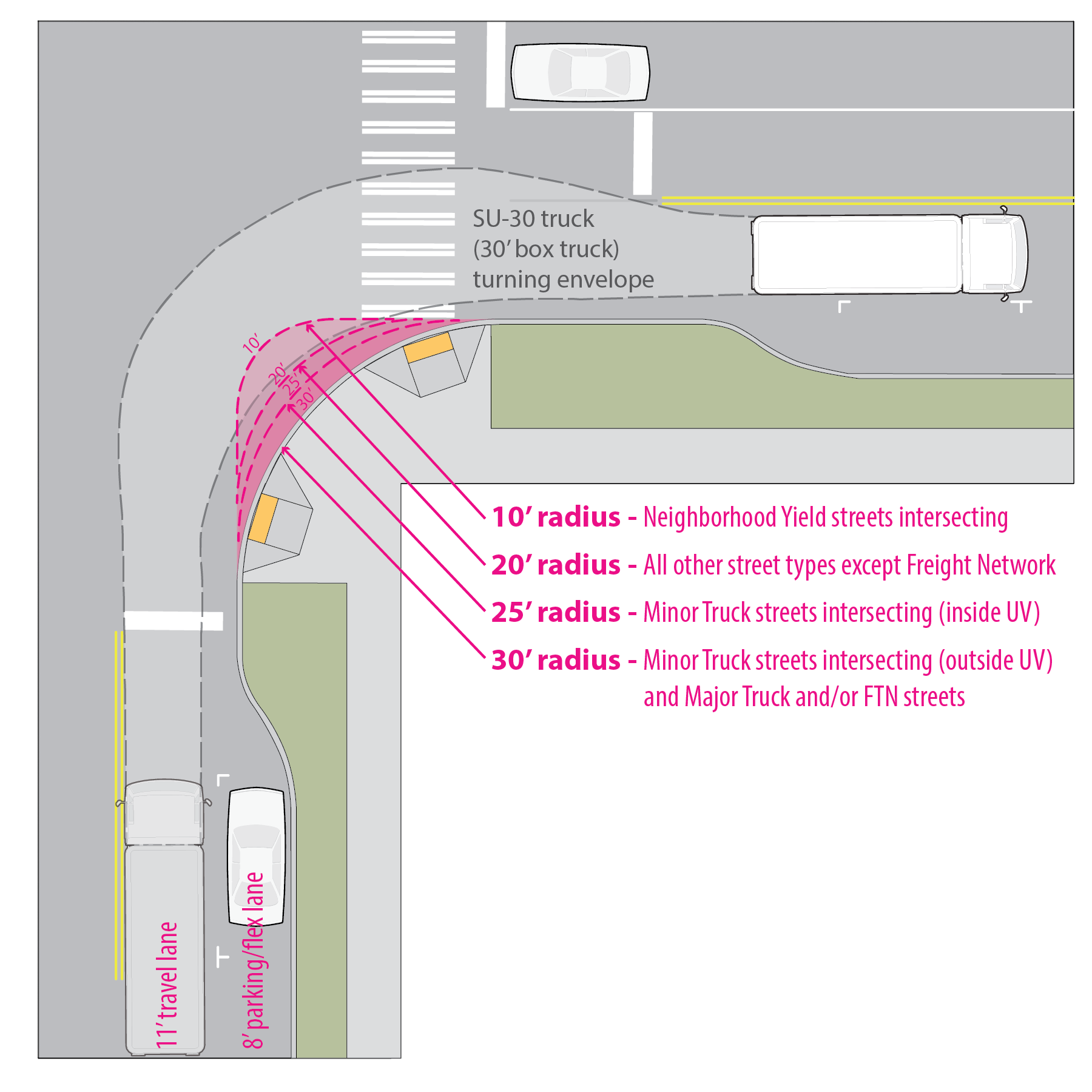
- Arterial Lane width: A variety of factors are considered when designing lane widths, including existing constraints within the right-of-way (such as building orientation, curb and sidewalk location, and on-street parking), right-of-way acquisition needs, current and projected truck traffic volumes, bicycle and pedestrian use, vehicular capacity needs, and the number of travel lanes. Truck type and dimensions are also a factor that should be considered when determining lane width.
|
Lane Type |
Standard Arterial Lane Width |
|
Parking lane |
8 feet |
|
Parking lane on bus route |
8 feet |
|
Through traffic lane |
11′ feet (10’ streets that are not part of Freight or Transit network and not a two-lane bidirectional roadway) |
|
Curb lane |
10’ or 11’ (12’ on Industrial Access street types) |
|
Bus only lane |
11 feet |
|
Turn only lane |
10 feet |
Intersection Concepts
The design of intersections in dense urban areas that can accommodate freight and other modes can be very challenging. Trucks can require large radius turns, resulting in significant right-of-way needs and longer pedestrian crossings. Considerations for type of design vehicle need to be made based on the presence or absence of the freight network when addressing turning movements. Access for trucks is important for delivery purposes as well as emergency response. At a minimum all streets should be designed to accommodate SU-30 trucks. The goal is to balance modal plans to keep streets accessible for freight, transit, and bicycles where designated, and creating positive environments for people walking.
Vehicle off-tracking
Most corner designs for trucks will need to be analyzed for vehicle swept path, also known as off-tracking. Off-tracking is the path a truck makes during left or right turns at intersections, and it does not follow the same path made by a regular size vehicle. AASHTO turning templates may be used for simple designs but provide limited flexibility for complex design scenarios. Another approach is to use specialized software, such as Autoturn, to complete the off-tracking analysis.
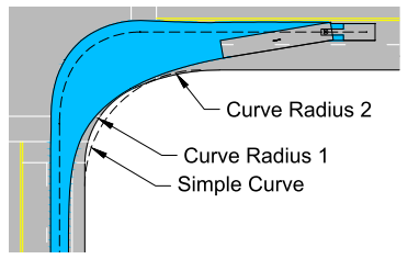
Multi-centered Corners (Compound Curves)
When trucks turn, particularly tractor-trailers, they sweep a path that can best be simulated by a series of curves. A simplified approach as seen in would use two or three compound curves to best match the pathway of the truck. By using this approach, the full swept path of the design vehicle can be designed for and larger vehicles checked for accommodation, if appropriate, while still minimizing the amount of roadway surface. Minimizing roadway surface also manages crossing distances, signal pole arm lengths, etc., and provides both safety and cost benefits to the project. These designs also allow for a tighter radius corner, which will help promote speed reduction for smaller vehicles making the turn. Figure BX illustrates the efficiencies gained with this design approach.
Design Application
- AASHTO Policy on Geometric Design of Highways and Streets Chapter 9 contains more information regarding compound curve design, including tables and exhibits. Note, the recommendations presented in Chapter 9 assume an outside lane to outside lane corner design and could be conservative on multi-lane roads given the definition for “design for” noted earlier in this document.
- Typically, designers will complete an analysis using a two- or three-centered curve design with a vehicle swept path software package (i.e., Autoturn) or turning templates. When using such software, the following guidance is recommended:
- Start and end the vehicle in the center of the exiting and receiving lanes
- Set the vehicle speed as follows:
- 10 miles per hour (mph) or greater for signalized intersections
- 5 mph for stop sign controlled or uncontrolled intersections
- In these analyses, designers seek to provide at least 1-foot (2-feet preferred) of clearance from vehicle body to the curb face at any portion of the corner
- Use 2-feet of vehicle clearance envelope in most situations so that vehicle path is unlikely to run onto the gutter pans at the curb and gutter, as well as provide a buffer for path variability to the curb face. Over shorter distances, 1-foot of clearance may be acceptable. A strengthening of the gutter may be required in these situations.
- Limit the use of multiple node points within the turn that change the turning radius, a single point-to-point corner path is preferred.
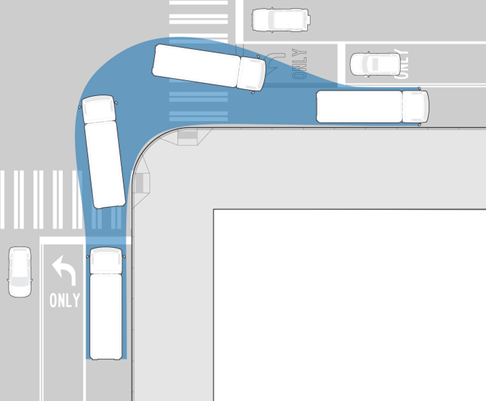
Setback Stop Bar Placement
Design Considerations
Stop bar location on both the street a truck is turning from, as well as the cross street approach the truck is turning into, can have a dramatic effect on the accommodation of truck turning movements. Stop bars can be set back from the intersection and crosswalk to provide room for the swept path of the turning vehicles. Additionally, not all lanes need to have the stop bar setback. On cross street approaches, this treatment is typically limited to the left-turn lane when such a lane is present as seen in Figure BY. For cross street approaches without a left-turn lane, the stop bar for the inside through lane can be set back.
Design Application
- Check stop bar placement for both left- and right-turning movements on both the street a truck is turning from as well as the cross street approaches (if accommodating and not designing for) for the specified design vehicle.
- Verify that the stop bar location does not exceed the maximum stop bar to street light distance as allowed by the Manual on Uniform Traffic Control Devices.
- Include supplemental lane markings so that cars have clear indication of the lane locations through the intersection.
- Take into consideration existing signal detection equipment and make adjustments as needed.
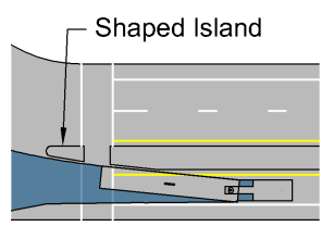
Crossing Islands
Crossing islands, sometimes called median refuge islands, provide a location in the median of the street for pedestrian refuge on wide roadways. They shorten the effective crossing distance at the expense of creating a two-stage crossing and additional delay for the person crossing the street. The advantages of reducing crossing distances are twofold. First it limits the amount of time a pedestrian is in a crosswalk and exposed to the traffic flow. Second, because signal designs can plan for a two-stage crossing, signal timing can be better optimized for traffic, including trucks, since pedestrian crossing times often dictate the minimum amount of time a signal must remain green.
The islands also provide an opportunity to visually enhance a street with landscaping or textured hardscape within the raised median island, taking care not to obstruct sightlines.
Design Application
Check for clearance using turning templates or software that simulates the turning movement of the design vehicle to accommodate trucks.
The island end can be shaped to better match the turning path of the truck as shown in Figure BZ. The crossing island may also be created with adaptive materials (like paint and flexi-posts) in order to better accommodate large turning vehicles.
Reflectorized markers mounted to the top of the island curb can help visibility at night.
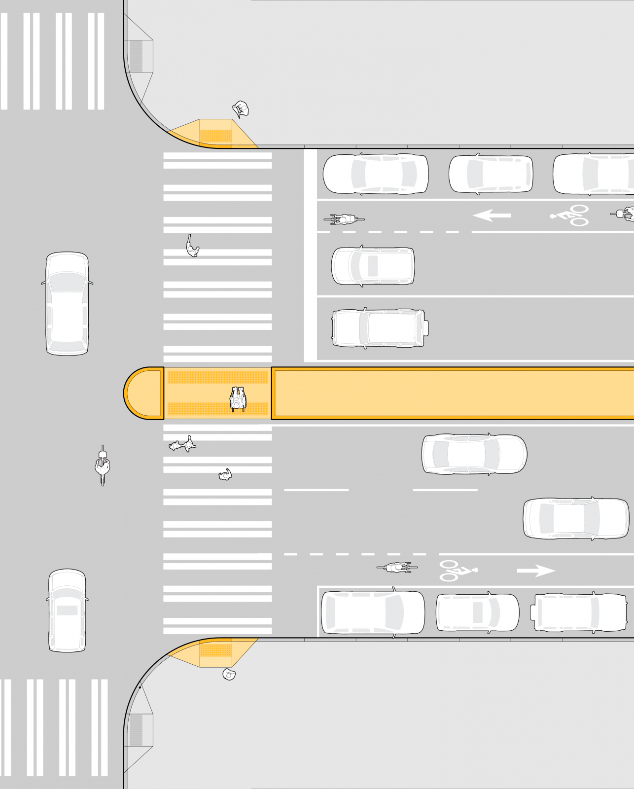
Green Bicycle Boxes
Bicycle boxes work best when several bicycles are anticipated to arrive at a signal and where visibility and conflict reduction with right-turning vehicles is important. On routes with a significant number of people on bicycles, the operational impact of preventing right turns on red for the waiting vehicles is offset by improved safety. A green bicycle box is helpful for routes that are also used as freight routes in order for drivers to better see bicyclists by situating them ahead of drivers at intersections. For more information see Bike Intersection Design.
Bicycle Signals
Provide an exclusive phase for people on bicycles, allowing them to move through the intersection unaffected by other traffic. Bicycle signals can be used to improve truck and bicycle safety at intersections by separating the turning and through movements of people on bikes and general traffic, and better managing that conflict point. The signals can be set to work in a number ways:
- As a leading bicycle interval (an early green), allowing the bicycles to “queue jump” through the intersection. This helps clear the bicycle lane before the green phase for vehicles starts.
- To separate bicycle movements from conflicting automobile turn movements.
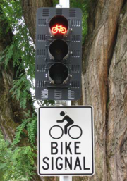
Design Application
- Make sure bicycle signal loop detection is provided and clearly marked. Alternative detection technologies include video, magnetomers, and microwave detection.
- Can be used in conjunction with setback bicycle lane stop bar to protect the person in a bicycle lane from encroachment by the path of large turning trucks. Make sure to align the bicycle signal loop detection with the setback stop bar.
Protected Bicycle Lanes
Protected bike lanes are defined by their separation from the sidewalk and the roadway. Generally, the Bicycle Master Plan (BMP) network avoids major truck streets where there are alternative routes available. However, when bike facilities are part of the BMP network, a protected bicycle lane is recommended to provide high visibility and predictability for all travelers. For more general information, see the Protected Bike Lanes page.
In addition to lateral separation and raised physical features, separation may also achieved by adjusting the elevation of the bike lane surface relative to the elevations of the sidewalk and general purpose roadway.
The “One Way Protected Bicycle Lane Mixing Zone” treatment shown in SS provides a transition to a shared right turn/bicycle lane when a buffered or protected bicycle lane is used on the street. On truck streets, the design vehicle can help inform the project by creating a mixing zone that is, at a minimum, the length of the design vehicle plus 10.0-feet.
Corners designed for the largest trucks create long crossing distances for pedestrians, increased when there are more than two lanes in each direction. One approach to managing long crossing distance is by using a median refuge island like the one shown in Figure AZ. This allows pedestrians to cross the street in two stages and may be a solution where space is available.
Similarly, an option to shorten crossing distances is a corner island (also known as a “pork chop” island), which can act as a refuge between a right-turn-only lane and through traffic. Such islands do expose the pedestrian to the right-turn stream of traffic, and the safety of that crossing should be considered including incorporation of traffic calming techniques, signage, and flashing beacons as ways to control and/or warn people driving about the crosswalk and requirement to stop. Such islands can also restrict trucks larger than the design vehicle from making the turn, so careful design is required, even going as far as using a larger design vehicle. Due to these caveats, this treatment is typically implemented only when other approaches have been exhausted.
Crosswalks should be checked to make sure minimum illumination levels are achieved, particularly at very large intersections. Additionally sight lines to the crosswalk for turning vehicles need to be kept clear from vegetation, parked cars, signs, and other obstructions.
Transit
Usually a street designed for transit is well suited for large trucks. Buses used for transit have similar design characteristics as truck traffic, and the modes often prefer the same relatively flat corridors. Roads with articulated buses typically have intersection designs that accommodate turning movements for the AASHTO articulated bus (A-BUS) design vehicle. When planning a project on these routes, review the design to ensure the truck design vehicle is accommodated, if applicable.
Clearances
Obstructions, such as signs, utility poles, and landscaping, can impede curb side clearances along a freight corridor. Therefore, it is important to consider the dimensions of the truck design vehicle when developing plans for the street side. References the Clearances section for vertical and lateral clearance standards.