Protected Bike Lanes
- Best Management Practice Description
- One-Way vs. Two-Way Protected Bike Lane Facility
- Elements of Protected Bike Lanes
- Protected Bike Lane Zones
- Accessible On-Street Parking and Protected Bike Lanes
On this page:
Best Management Practice Description
Protected bike lanes are exclusive bicycle facilities where bicyclists are separated from sidewalks and motor vehicle traffic by physical features intended to prevent encroachment. Protected bike lanes differ from standard bike lanes in two ways: there is a lateral separation between the protected bike lane and the nearest general purpose lane, and there is some type of physical feature that provides positive separation between the protected bike lane and the general purpose lane. The physical feature may include such things as curbs, flexible delineator posts, permanent planters, or other raised features. In some instances parked cars may function as the physical separator; however, in that case special attention must be given to the buffer between the parked cars and the protected bike lane. Protected bike lanes may be one-way or two-way.
One-Way vs. Two-Way Protected Bike Lane Facility
Because protected bike lanes include features that provide positive separation from motor vehicle traffic, they may be designed to accommodate one-way or two-way bicycle travel. There are many factors that must be considered when determining the appropriate design, including access, network connectivity and functionality, traffic operations, number of driveways and intersections, and topography.
One-way protected bike lanes have a number of advantages over two-way protected bike lanes:
- More intuitive to all roadway users,
- May require fewer modifications to signal operations at intersections,
- Fewer conflicts at driveways,
- Provide access to both sides of the street, thereby reducing the need for users to cross the street where there are an equal number of destinations on either side of the street,
- No potential for conflict between bicyclists traveling in the opposite direction, which may be a concern on segments with grades greater than 5 percent.
For these reasons, one-way protected bike lanes are the preferred treatment and should be considered before two-way protected bike lanes.
Two-way protected bike lanes are appropriate where:
- One side of the street has fewer points of potential conflict such as driveways, intersections, or turning motor vehicles,
- Destinations on one side of the street generate significantly more demand than the opposite side of the street,
- Contra-flow bicycle travel is desired on a one-way street,
- A better connection with another bicycle facility can be made,
- Operations of the street preclude placement of a one-way facility.
- Topography limits route choice and network functionality,
- The right-of-way is highly constrained precluding the installation of two one-way facilities while also achieving minimum travel lane and sidewalk width standards.
Detailed design requires careful consideration for the provision and design of: pedestrian crossings, accessible parking, intersection geometrics and signal operations, commercial loading zones, transit stops and driveways. Tables 1a and 1b summarize planning considerations that should be considered when selecting the configuration of a Protected Bicycle Lane.
Table 1a: Example Protected Bike Lane Configurations on a One-Way Street
|
Corridor-Level Planning Considerations
|
One-Way PBL |
Contra-Flow PBL |
One-Way PBL plus Contra-Flow PBL |
Two-Way PBL |
 |
 |
 |
 |
|
|
Access to Destinations |
Limited access to other side of street |
Limited access to other side of street |
Full access to both sides of street |
Limited access to other side of street |
|
Network Connectivity |
Does not address demand for contra-flow bicycling, may result in wrong way riding |
Requires bicyclists traveling in the direction of traffic to share the lane; contra-flow progression through signals may be less efficient |
Accommodates two-way bicycle travel, but contra-flow progression through signals may be less efficient |
Accommodates two-way bicycle travel, but contra-flow progression through signals may be less efficient |
|
Continuation into Non-Protected Bike Facility |
Natural transition |
Natural transition* |
Natural transition* |
Requires bicyclists traveling in one direction to cross motor vehicle traffic |
|
Conflict Points |
Peds and turning drivers expect concurrent bicycle traffic |
Peds and turning drivers may not expect contra-flow bicycle traffic |
Peds and turning drivers may not expect contra-flow bicycle traffic |
Peds and turning drivers may not expect contra-flow bicycle traffic |
|
Intersection Operations |
May use existing signal phases; bike phase may be required depending on volumes |
Typically requires additional signal equipment; bike phase may be required depending on volumes |
Typically requires additional signal equipment; bike phase may be required depending on volumes |
Typically requires additional signal equipment; bike phase may be required depending on volumes |
* Bicyclists traveling in contra-flow direction may continue riding the wrong way if they are not channelized properly to the street or a bikeway at contra-flow termination points.
Table 1b: Example Protected Bike Lane Configurations on a Two-Way Street
|
Corridor-Level Planning Considerations |
One-Way PBL Pair |
Curbside |
Median |
 |
 |
 |
|
|
Access to Destinations |
Full access to both sides of street |
Limited access to other side of street |
Limited access to both side of street |
|
Network Connectivity |
Accommodates two-way bicycle travel |
Accommodates two-way bicycle travel |
Accommodates two-way bicycle travel |
|
Transition to Non-Protected Bike Facility |
Natural transition |
Requires bicyclists traveling in one direction to cross motor vehicle traffic |
Requires bicyclists traveling in both directions to cross motor vehicle traffic |
|
Conflict Points |
Peds and turning drivers expect concurrent bicycle traffic |
Peds and turning drivers may not expect contra-flow bicycle traffic |
Peds and turning drivers may not expect contra-flow bicycle traffic, but median location minimizes interaction |
|
Intersection Operations |
May use existing signal phases; bike phase may be required depending on volumes |
Typically requires additional signal equipment; bike phase or turn restrictions are required at signals |
Typically requires additional signal equipment; bike phase or turn restrictions may be required depending on volumes |
Elements of Protected Bike Lanes
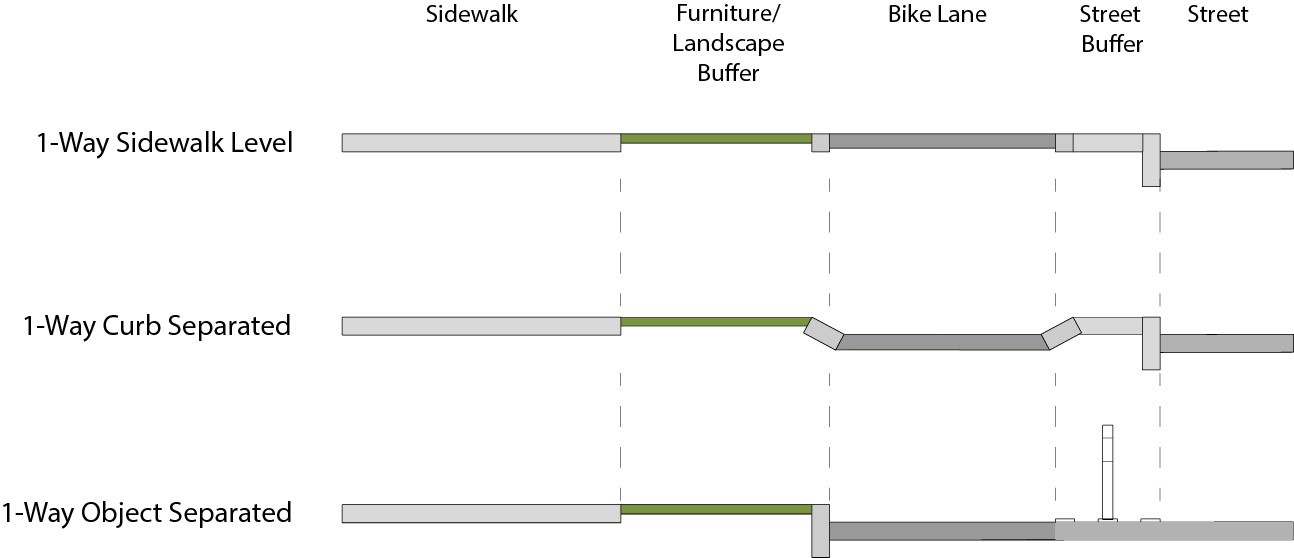
Protected bike lanes are defined by their separation from the sidewalk and the roadway. In addition to lateral separation and raised physical features, separation may also achieved by adjusting the elevation of the bike lane surface relative to the elevations of the sidewalk and general purpose roadway. There are two basic configurations for protected bike lanes, as shown in Figure T:
- Curb Separated. Curb separated protected bike lanes are composed of a bike lane that may be at the same elevation as the sidewalk or at street-level. If there is no buffer to the sidewalk, the PBL should be set at an elevation below sidewalk level, or the surface should provide visual contrast with the sidewalk through use of color, different paving materials, and or pavement markings to encourage correct use and reduce conflicts between bicyclists and pedestrians.
- Object Separated. Object separated bike lanes are built at the same level as the surface of the street. Separation from traffic or parking is thus provided entirely by a painted median and a physical separation element (e.g. curb, planter, flex delineators).
Lateral Separation Elements
Lateral separation elements include pavement markings and one or more vertical physical features that create the physical separation from motorized vehicle traffic and/or parking.
Summary Table:
| Buffer between bike lane and parking | 3′ | |
| Flexible delineators | ||
| Height | 28″ minimum -36″ maximum | |
| Offset | 12″ minimum offset from edge of bikelane | |
| Planters | ||
| Height | 28″ minimum -36″ maximum | |
| Offset | 12″ minimum offset from edge of bikelane | |
Striped Median: Guidance for marking the buffer zone is provided in Chapter 3D of the MUTCD ‘Markings for Preferential Lanes’. The striped median must also contain a physical separation element (described below) to classify the bicycle lane as a protected bike lane. Retroreflective pavement markers (RPMs) may be used to supplement physical separation elements, particularly where spacing between these elements exceeds 30′. RPMs should be inwardly offset 4″ from the outside stripe of the buffer rather than placed directly on the stripe. RPMs should be placed mid-point between physical separation elements.
Physical Separation Elements: Physical separation elements may consist of a wide range of potential treatments to provide a physical barrier such as flexible delineators, raised curbs, planters, parking lanes, or other objects as approved by SDOT. The spacing of the physical separation element should be determined by the need to protect the bicycle lane from vehicle encroachment. On facilities with higher vehicle volumes and speeds use permanent separation treatments.
Curb Medians: Curb medians may be constructed to create a permanent, physical barrier between the bike lane and travel or parking lane. This treatment is preferred on high volume streets where speeds are anticipated to exceed 30 mph. In constrained conditions (bike lane width below 6.5′) an 8″ single sloped block curb should be considered (Standard Plan 413b) adjacent to the bike lane to reduce the chance of a pedal strike on the curb. Curb median designs should maintain proper drainage of the site, particularly in retrofit projects that do not include underground drainage system alterations. For retrofit facilities gaps between vertical objects or curb openings in raised medians may be used to channelize stormwater across the street buffer towards existing catch basins along the sidewalk buffer. These median curb cuts may be open channels or covered with steel plates. Steel plates should be considered in areas where parallel parking is proposed and should meet AASHTO HS20 loading conditions to accommodate traversing people. For reconstruction projects supplementary catch basins in the street buffer or more frequent curb cuts should be considered in order to control the speed and spread of water within the bike lane.
Parking: Occupied on-street parking can be an effective way to separate a bike lane from adjacent motor vehicle lanes assuming a minimum 3′ buffer can be placed between the parking and bike lanes. The parking lane must be continuously occupied in order to qualify as the physical separation element for a protected bike lane. Off-peak parking lanes that function as active traffic lanes must be supplemented with physical separation elements when adjacent to protected bike lanes.
Flexible Delineators: Flexible delineators (also known as tubular markers) should be used for temporary treatments rather than a permanent design element and should conform to the current MUTCD specifications (Section 3H.01) for size, color and retro reflectivity. SDOT currently has two vendors please contact Transportation Operations for post specifications. They should be a minimum of 28″ and a maximum of 36″ in height and offset a minimum 12″ from the edge of bike lane. Delineator posts should generally be placed along the center of the median, but they may be shifted to improve maintenance vehicle access or to create additional effective width for the bike lane, parking lane, or travel lane as conditions necessitate. The delineators should be placed a minimum of 10′ on center up to a maximum of 40′ on center. The spacing should be determined by the need to protect the bicycle lane from vehicle encroachment such as at locations where there is an observed demand for curbside access for delivery, or pick-up and drop-off.
Planters: Planters may be used to create a more permanent or aesthetically pleasing form of separation. Their use is limited to locations where the chance of motor vehicle encroachment from adjacent travel lanes is unlikely due to the speed and context of the street, or the presence of full time parking. They should be a minimum of 28″ and a maximum of 36″ in height and offset a minimum 12″ from the edge of bike lane. Plant choice should account for mature plants. Delineator posts should generally be placed along the center of the buffer. The planters may be placed to form a continuous barrier or spaced up to a maximum of 40′ on center. The spacing should be determined by the need to protect the bicycle lane from vehicle encroachment from parking or loading vehicles such as at locations where there is an observed demand for curbside access for delivery, or pick-up and drop-off.
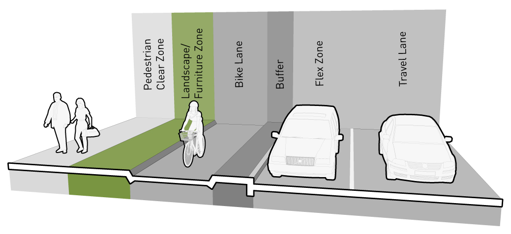
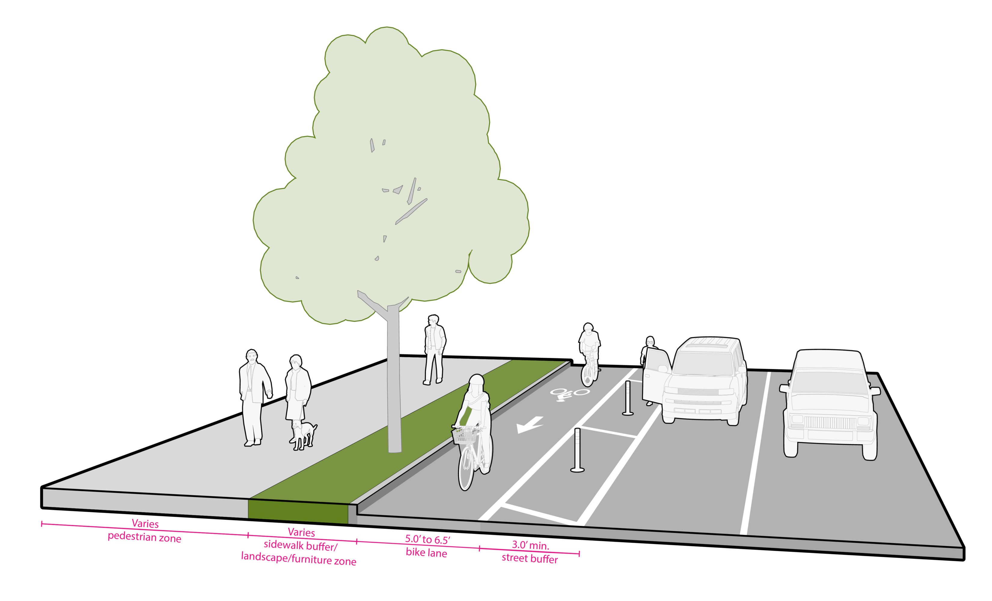
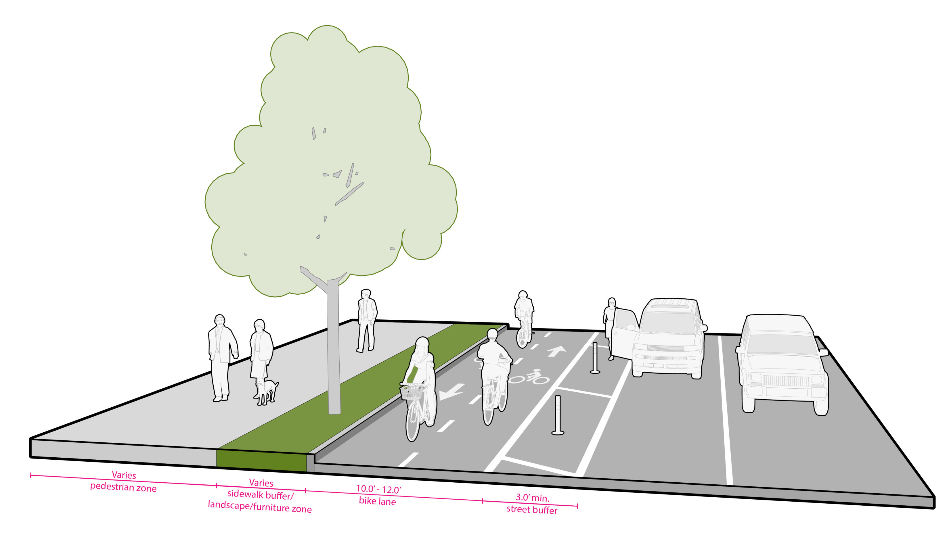
Protected Bike Lane Zones
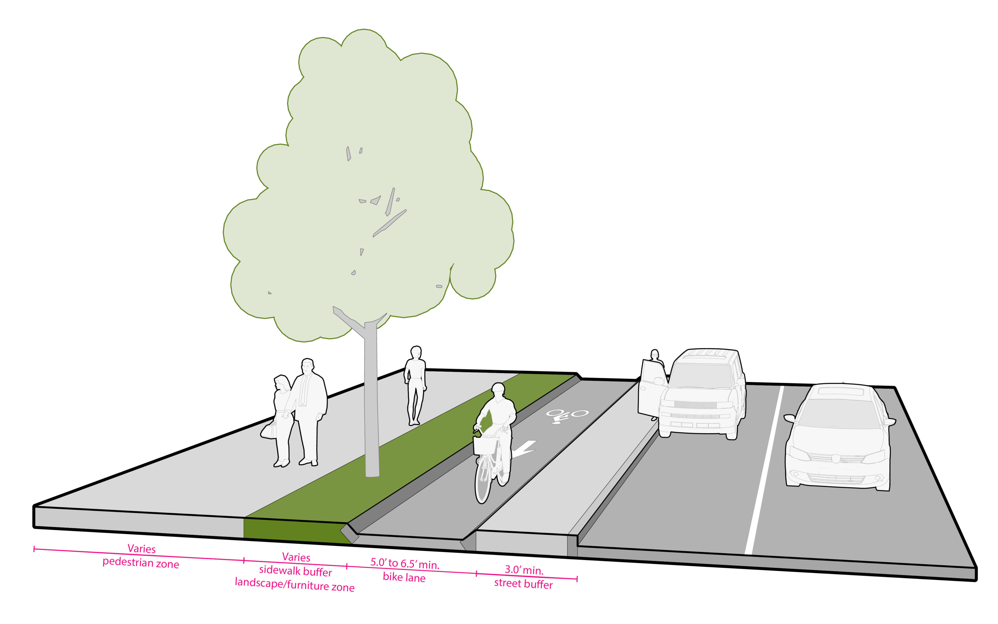
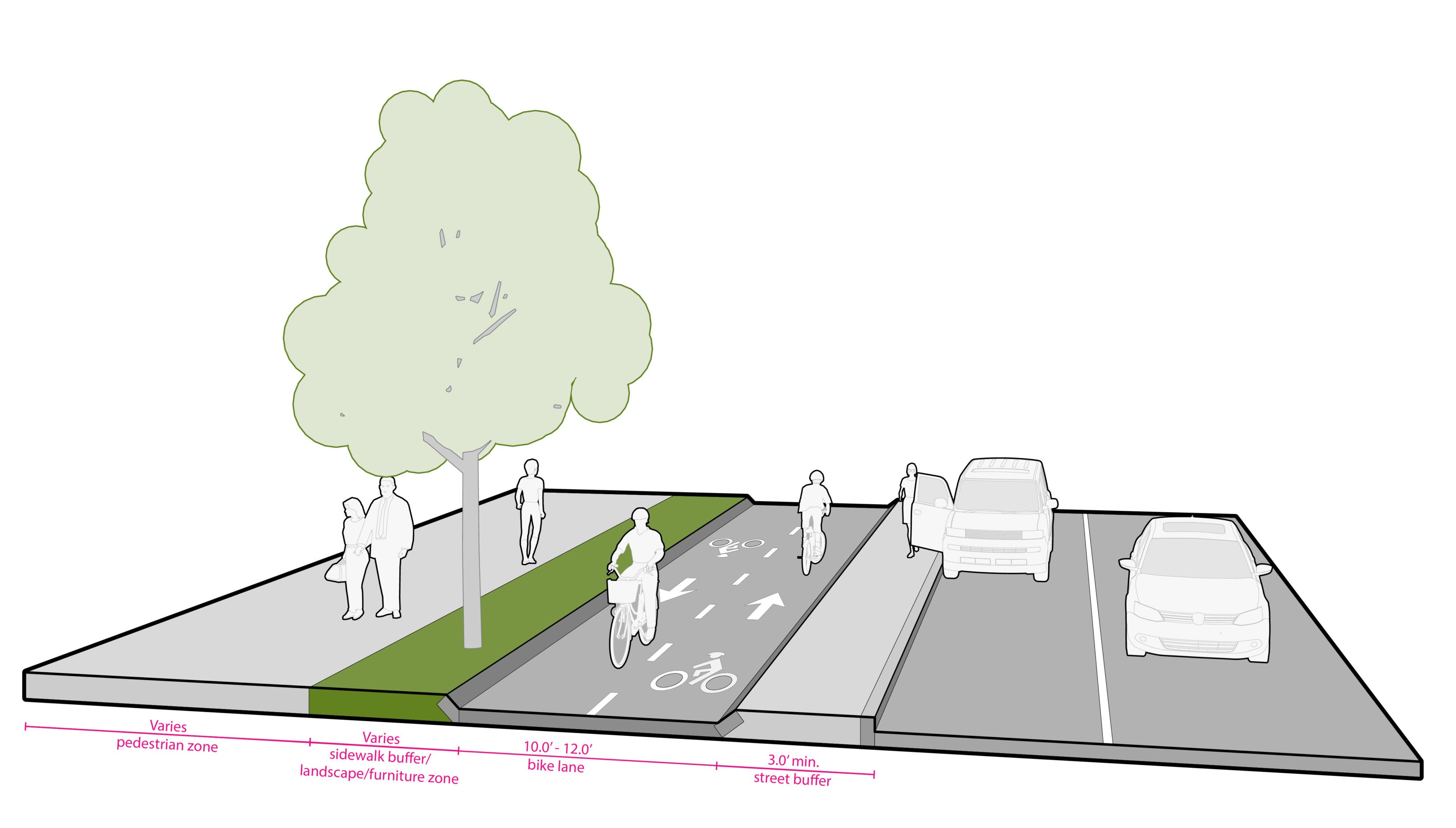
Each of the types of protected bike lanes in Figure V and Figure W are composed of 3 zones: the street buffer zone, the bike lane, and the sidewalk buffer zone (also referred to as the landscape/furniture zone) as shown in Figure U.
Summary table:
| Street buffers | ||
| Adjacent to parking | 3′ | |
| Tree clearance from bike lane | ||
| Horizontal | 3′ | |
| Overhead clearance | 10′ | |
| Bike lane – pedestrian clear zone elevation separation | 2″ | |
Street Buffer Zone
The street buffer zone provides lateral separation between the bicycle lane and a parking or travel lane. Physical separation is provided by a curb median or vertical object placed in the street buffer zone, as described below.
Street Buffer Zone Design Standards:
Street Buffer Zone Width: Appropriate street buffer widths vary greatly depending on the degree of separation desired, right-of-way constraints, and the types of elements or uses that are to be accommodated within the buffer. In general, street buffer width should be maximized to provide greater separation between bicyclists and adjacent vehicle lanes and improve visibility between motorists and bicyclists at intersections and driveways (See Bicycle Intersection Design section). Street buffers should be 3′ where the buffer is adjacent to parking; the buffer may be narrowed to a minimum of 2′ in constrained conditions (such as locations adjacent to an ADA parking stall) through a deviation.
The street buffer zone shall be designed to ensure the bike zone drains properly. This can be a significant issue for protected bike lanes that are retrofitted into existing streets, as it may be necessary to maintain positive drainage to the original inlets (which are usually curbside) across the vertical barriers used in the street buffer zone.
Street Buffer Zone Design Guidance:
Street buffers also affect bicyclists’ safety at intersections, including driveways and alley crossings. Street buffer widths that result in a recessed crossing between 6′ and 16.5′ from the motor vehicle travel lane have been shown to significantly reduce crashes at uncontrolled separated bike lane crossings. This offset improves visibility between bicyclists and motorists who are turning across their path, and creates space for motorists to yield. (See Bicycle Intersection section)
It is important that a corridor-wide perspective be maintained during the evaluation and design process, as excessive lateral changes between midblock sections and intersections may result in an uncomfortable bicycling environment. The designer will need to carefully consider intersection operations as the horizontal alignment is determined.
Transit boarding and alighting typically occur in the street buffer zone. See the Transit Design Section for additional design considerations.
Sidewalk Buffer Zone
The sidewalk buffer zone is located between the protected bike lane and the pedestrian zone.
The landscape/furniture zone functions as the sidewalk buffer zone for a street-level protected bike lane.
Design Guidance
There is a wide range of potential treatments for the sidewalk buffer zone. In ideal conditions, the buffer may provide space for landscaping, street furniture, or other physical elements to emphasize separation between pedestrians and bicyclists. When placing the bike facility adjacent to street trees, horizontal separation must be 3’ from the tree trunk and overhead clearance from the bike facility to the street tree canopy should be 10′.
For sidewalk-level protected bike lanes where provision of dedicated buffer space between the bike lane and sidewalk is not possible, separation can be defined by a change in elevation or an edge treatment that provides visual contrast and a detectable surface for visually impaired persons. For sidewalk level protected bike lanes where there are likely to be high volumes of pedestrians and/or bicyclists, it is preferable for there to be a minimum 2″ elevation difference between the pedestrian clear zone and the bike lane. This is to discourage improper use of either the bike lane by pedestrians or the sidewalk by bicyclists while providing a detectable edge for visually impaired persons. This visual delineation should extend to the intersection in order to encourage compliance from the point of entry of the bike lane and sidewalk. Signs or pavement markings may also be considered for sidewalk level facilities to reinforce appropriate use.
A detectable surface should also be provided for visually impaired persons. The use of detectable warnings (i.e. truncated domes) should be reserved for locations where pedestrians are channelized to cross the protected bike lane or the roadway. The use of contrast-colored strips with ridges running parallel to the direction of travel can be considered for locations where the sidewalk and protected bike lanes are built at the same elevation. This type of strip assists low vision persons in determining the location of the edge of the sidewalk when a vertical drop to the protected bike lanes (i.e. a sidewalk curb) is not provided.
Sidewalk Level Protected Bike Lane Additional Guidance:
Sidewalk level protected bike lanes are composed of a bike lane that is at the same (or similar) elevation as the sidewalk and separated from the roadway by standard vertical curb and street buffer.
A minimum 2′ buffer (3′ where curbside parking is present) should be provided between the bike lane and the adjacent travel lane or flex zone. There are a variety of ways to design this buffer. It can consist of a landscape strip, or where parking/loading is present, a hardscaped loading area. Occupied on-street parking may provide an additional buffer between a sidewalk level bike lane and vehicle travel lanes; however, it requires special design consideration at intersections, driveways, and alleys for maintaining appropriate sight triangles.
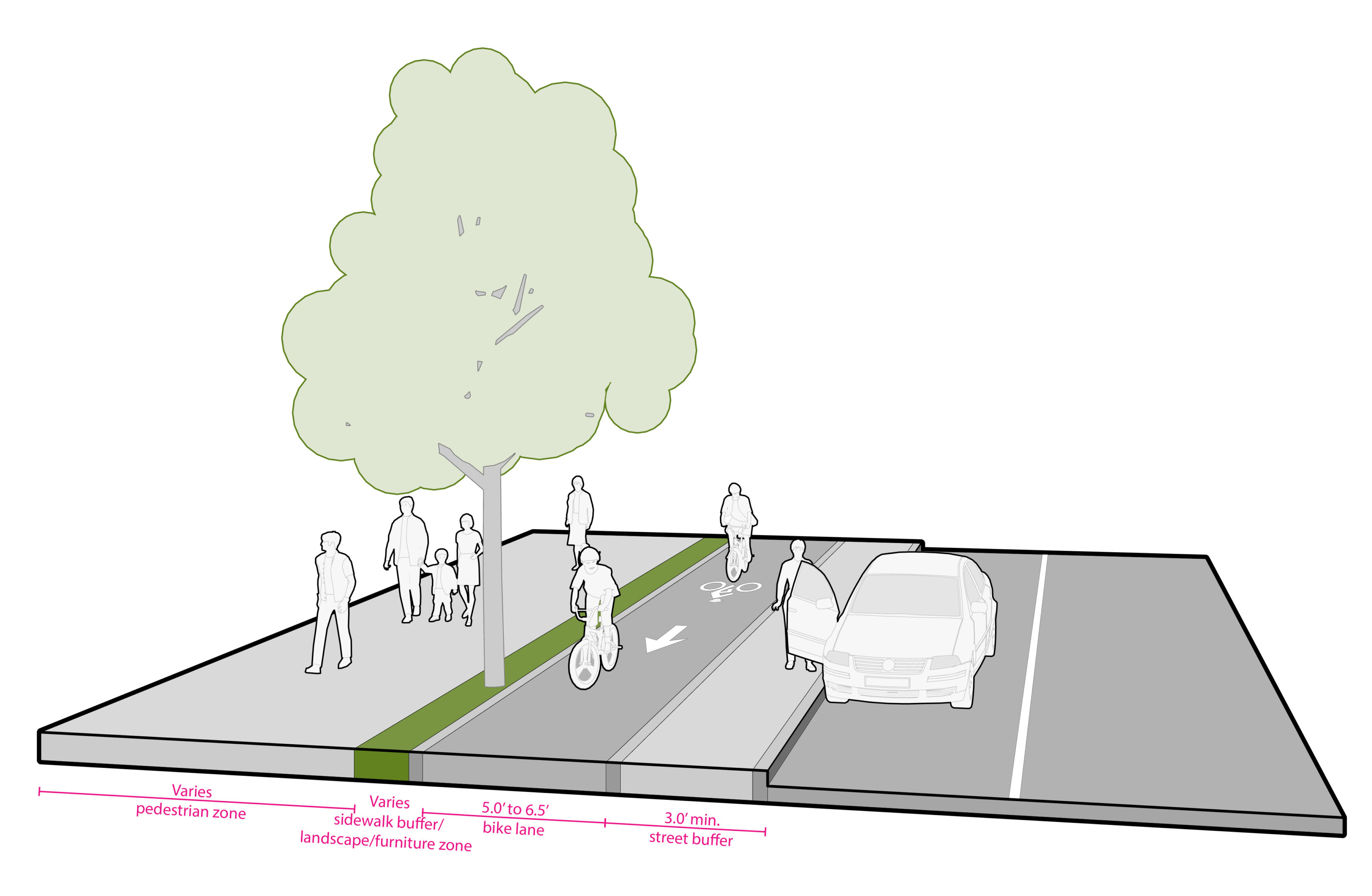
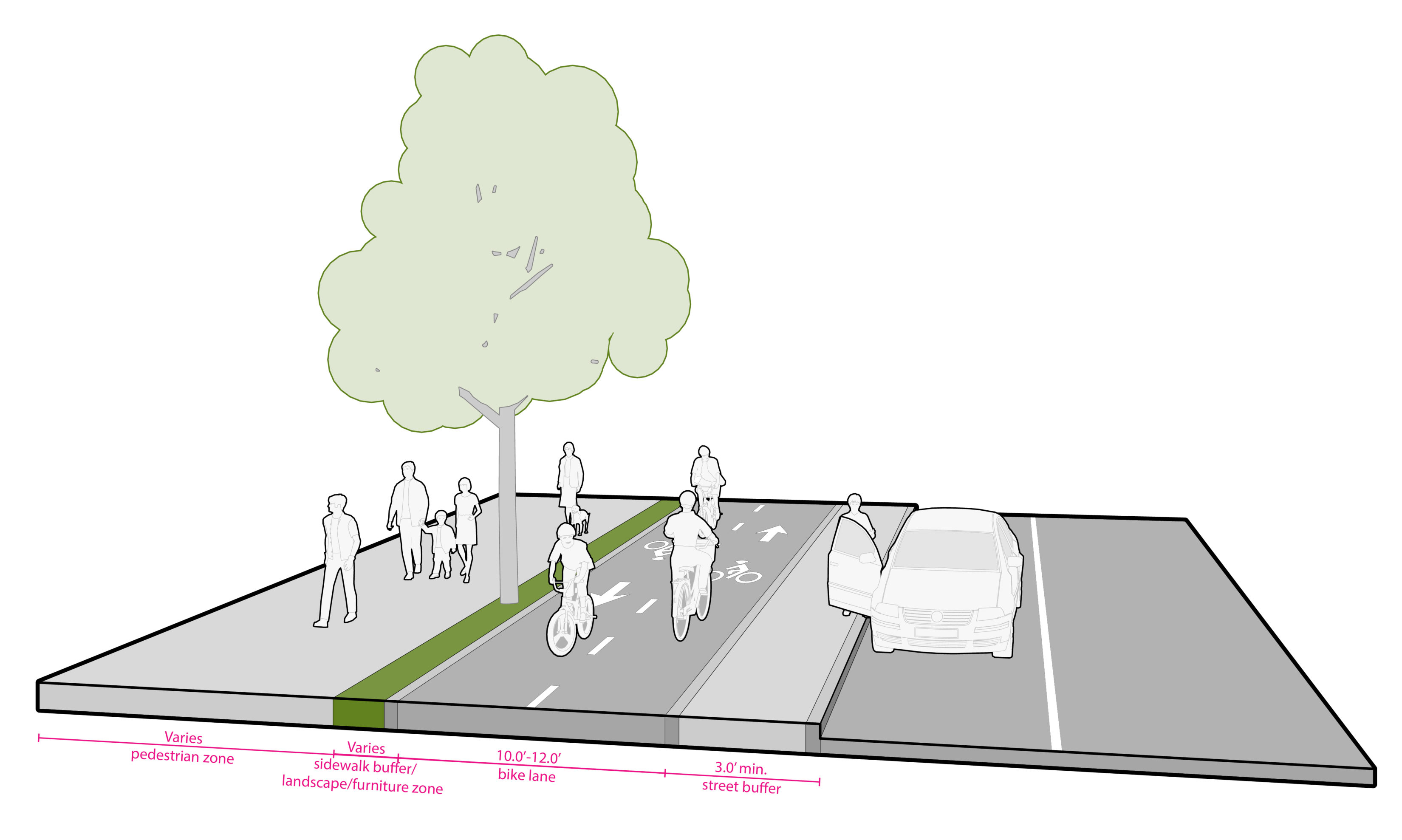
Bike Lane Zone
The bike lane zone is the space provided for the exclusive use of bicyclists.
Design Standards
Bike Lane Widths: Table X provides widths of protected bike lanes for one-way and two-way operation.
Table X Protected bike lane minimum widths
|
One-Way |
Two-Way |
|
|
Street-level |
5′ |
10′ |
|
Sidewalk-level |
5′ |
10′ |
Design Guidance
Bike Lane Surface: The surface of the bike lane should be smooth, stable and slip resistant. The primary surface types are asphalt and concrete. Longitudinal or frequent horizontal seams (such as those common with concrete) can reduce the quality of the riding surface. Concrete joints should be saw-cut to provide a smooth riding surface. If concrete slab seams are within a bike lane, the seams should be treated to provide a smooth riding surface that won’t catch tire wheels
Where the bike lane is flush with the surface of the adjacent sidewalk, the selection of the bike lane surface material should provide a contrasting appearance.
Utility covers and drain grates: Utility covers and drainage structures should be located outside of the surface of the bike lane where feasible. Where they are unavoidable, utility covers in the bike lane should be flush with the roadway surface. Drain grates must be designed such that narrow tires cannot get caught. When new drain grates are installed or existing drain grates replaced, they must conform to the grate design specified in Standard Plan 265.
Setbacks: Fixed objects should be set back 12″ from the bike lane. If it is not possible to meet required set back for necessary signing, consider alternative placement or materials that yield on impact.
Pavement Markings: Standard bike lane symbols and arrows should be provided in bike lanes. In some cases, the size of the symbols and arrows may need to be reduced to fit within the lane. Green pavement markings should be reserved for conflict points including driveways and intersections (See Bicycle Intersection section) and designed in coordination with SDOT. Two-way protected bike lanes should have solid yellow centerline a minimum 20′ in length at intersection approaches. Centerline markings may be desirable in other locations. See the AASHTO Guide for the Development of Bicycle Facilities for additional guidance on the use of centerline markings.
Signage: Signage is typically not required to identify the bike lane. R10-11 signs may be considered at locations with a high volume of conflicting traffic, such as at major driveways or crossings with major shared-use paths.
Accessible On-street Parking and Protected Bike Lanes
Where designated on-street parking is provided, accessible parking must be provided. Refer to current Public Rights of Way Accessibility Guidelines (PROWAG) published by the U.S. Access Board for more information. These spaces must be provided on the block perimeter where on street parking is marked or metered. A priority for accessibility is locating the parking spaces where the street is most level and, ideally, at the end of a block face with access to existing curb ramps. SDOT determines the suitability for the parking space on the end of block face based on grade, presence of trees or other objects in the required clear zone.
If a project affects at least one block face, including street resurfacing projects, that would clearly impact marked or metered parking provisions, then the project must use the table provided to determine how many accessible parking spaces would need to be installed on the block perimeter. Exact location needs to be approved by SDOT.
Required Proportion of Accessible Spaces in Relationship to Total On-Street Marked or Metered Parking Spaces
|
# of Parking Spaces |
Typical Corresponding Block Length |
Required # of Accessible Spaces |
|
1 to 25 |
450′ |
1 |
|
26 to 50 |
900′ |
2 |
|
51 to 75 |
1,350′ |
3 |
|
76 to 100 |
1,800′ |
4 |
|
101 to 150 |
2,700′ |
5 |
|
151 to 200 |
3,600′ |
6 |
|
201 and over |
4% of total |
*This length assumes an 18′ parking stall length. Where parking pay stations are in use and parking spaces are not marked, the length of an individual parking stall should be assumed to be 20′.
See PROWAG section R309 On-Street Parking Spaces for design guidance for parallel and angled parking spaces.
Accessible On-Street Parking Design Guidance
In many cases, the accessible parking may be provided on block faces that do not conflict with protected bike lane alignment. However, a priority for accessibility is locating the parking spaces where the street is most level and, ideally, closest to obvious destinations such as building entrances. Under these circumstances it may be necessary to include accessible parking on the same block face as a protected bike lane. Providing accessible parking spaces at the end of a block often affords the most flexibility in designing around the protected bike lane. A painted access aisle without any vertical elements provides space to deploy a lift and allows a vehicle to park in the buffer to deploy a left-side lift, if necessary.
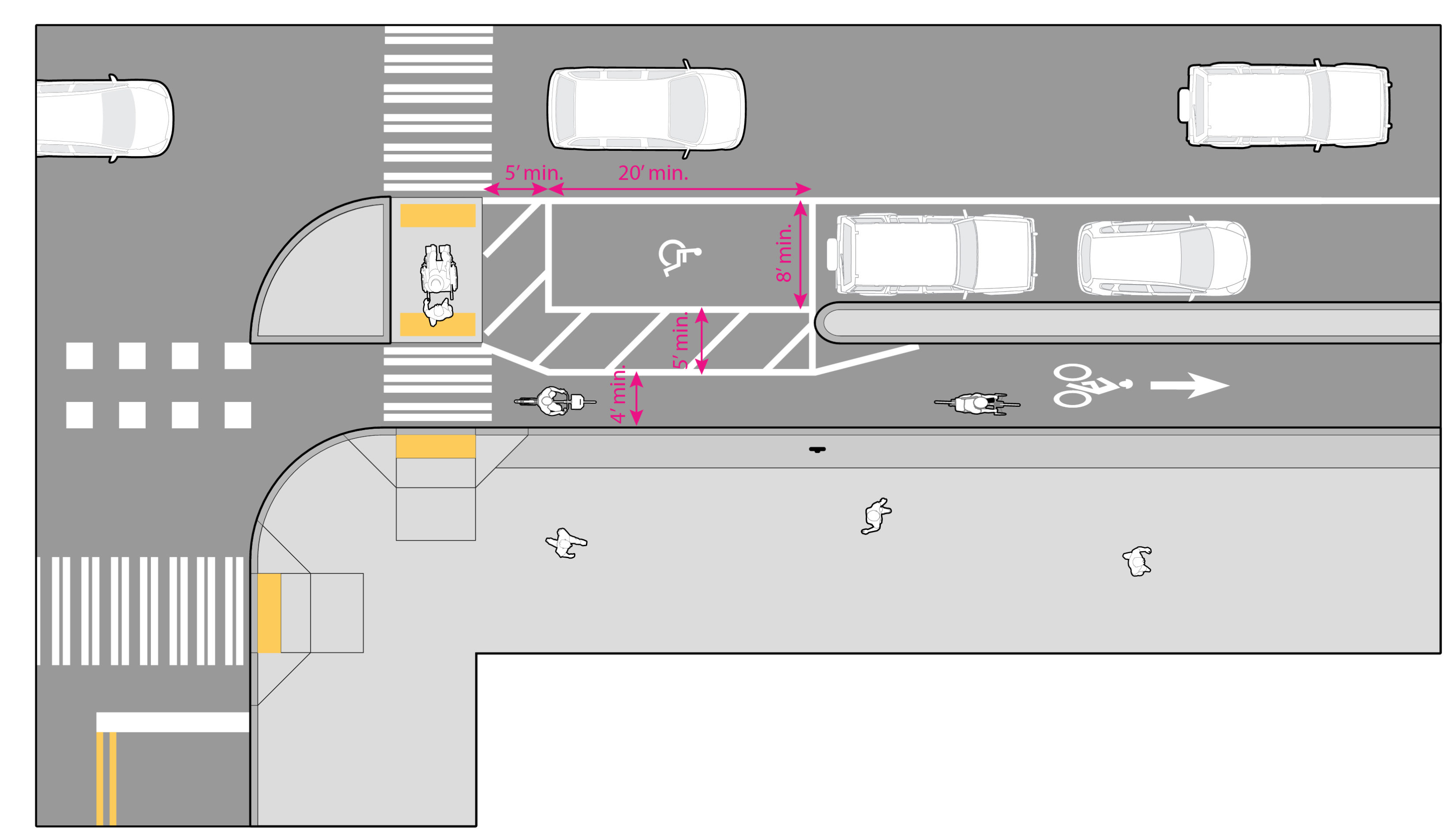
Figure AB shows a typical layout of an accessible parking space provided in the public right-of-way.
In the event that accessible parking must be provided midblock, refer to FHWA’s Separated Bike Lane Planning and Design Guidelines for design guidance.
If you need an accommodation to participate in a City activity, program, or service, contact the City of Seattle ADA Coordinator at adacoordinator@seattle.gov or 206-684-2489.